Method of characterising an LED device

Inactive Publication Date: 2012-11-15
NXP BV
View PDF8 Cites 11 Cited by
  • Summary
  • Abstract
  • Description
  • Claims
  • Application Information

AI Technical Summary

Benefits of technology

[0010]The method may further comprise determining at least one further value of the characteristic resistance after respectively at least one further part of the operation life, and predicting an end of an operational lifetime may comprise extrapolating an evolution or slope of the characteristic resistance against operational lifetime. This may involve a linear extrapolat

Problems solved by technology

Similar to many other light sources, the light output from an LED decays over time, ultimately leading to LED failure.
However, since the replacement schedules generally try to completely avoid pre-replacement failure, and there is a significant spread in the time at which an LED may be expected to fail, many LEDs are replaced considerable before a likely failure, which is clearly wasteful; alternatively, if the replacement schedu

Method used


Image

  • Method of characterising an LED device
  • Method of characterising an LED device
  • Method of characterising an LED device

Examples


Embodiment Construction

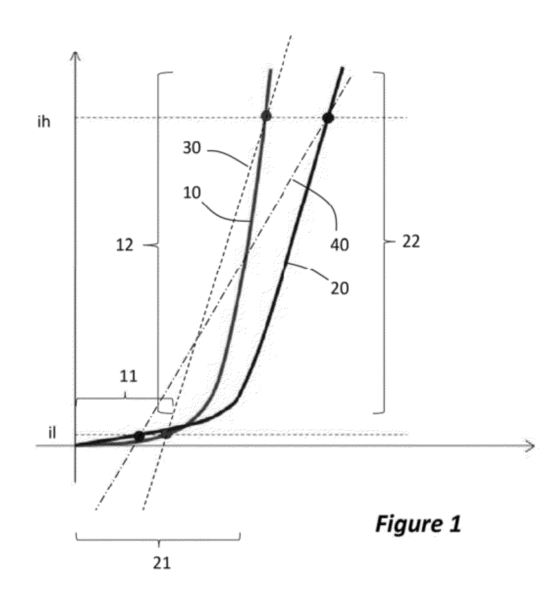
[0026]FIG. 1 is a graph of typical forward bias current-voltage (IV) plots for an LED. Curve 10 is a typical curve for a “new” or pristine LED, that is to say, an LED which is at the start of its operational lifetime. The curve is characterised by having low leakage current. This is shown towards the left of the curve a region 11, below the ‘knee’ of the curve. Further, above the ‘knee’, the curve is generally steep as shown at region 12.

[0027]The figure further shows a corresponding IV-characteristic 20 of a typical aging LED. Relative to the new, or pristine, LED curve 10, this curve 20 has a somewhat higher leakage at low forward bias, shown at region 21, and typically a somewhat less steep slope at higher forward bias, as shown at 22.

[0028]The curve may be understood as follows: as the LED gets older, the metal—semiconductor contact of the LED may deteriorate, leading to extra resistance at those contacts. This increased contact resistance leads to an increased effective resista...


PUM


Abstract

A method of characterising an LED, as well as an integrated circuit using this method, based on a so-called characteristic resistance, in which the LED is operated at a first, relatively low, operating current and then at a second, relatively high, operating current. From the ratio between the difference between the forward voltages at these two operating currents, and the difference between the operating current, the characteristic resistance is determined. The characteristic resistance is measured at two or more moments during the operational lifetime of the device, and a prediction or estimate is made in relation to the total operational lifetime of the devices, from the evolution or change of the characteristic resistance.

Description

[0001]This application claims the priority under 35 U.S.C. §119 of European patent application No. 11165352.3, filed on May 9, 2011, the contents of which are incorporated by reference herein.FIELD OF THE INVENTION[0002]This invention relates to method of characterising a light emitting diode (LED) device. It further relates to LED drivers configured to operate such a method.BACKGROUND OF THE INVENTION[0003]Due to their known advantages, such as high efficiency in terms of lumens per watt, small form factor and durability, LEDs are used as light sources in high performance lighting fixtures. LEDs are increasing preferred light sources in difficult-to-replace lighting fixtures, such as street lights, traffic signal lights and in fixture that require high reliability, such as automotive lights, for instance for safety reasons.[0004]Similar to many other light sources, the light output from an LED decays over time, ultimately leading to LED failure. In order to avoid complete failure, ...

Claims


Application Information

Patent Timeline
IPC IPC(8): G06F19/00H05B44/00
CPCG01R31/2635H05B33/0893G01R31/2642H05B45/58
Inventor NGUYEN, VIET HOANGBANCKEN, PASCAL
Owner NXP BV
Why Eureka
Try Eureka