
Saw tooth for circular saw

a circular saw and saw tooth technology, applied in the field of circular saw teeth, can solve the problems of increased fuel consumption, reduced productivity, and relatively quick wear of saw teeth, and achieve the effects of reducing productivity, reducing fuel consumption, and increasing fuel consumption

Active Publication Date: 2012-11-22
MICACCHI MAURICE
View PDF6 Cites 9 Cited by
  • Summary
  • Abstract
  • Description
  • Claims
  • Application Information

AI Technical Summary

Benefits of technology

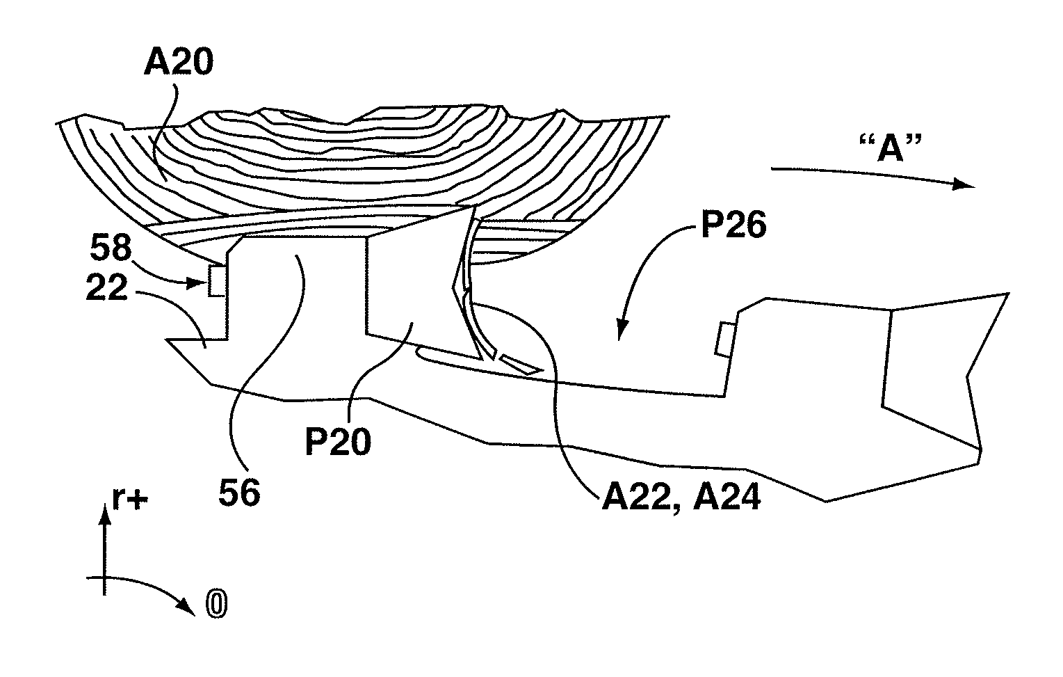
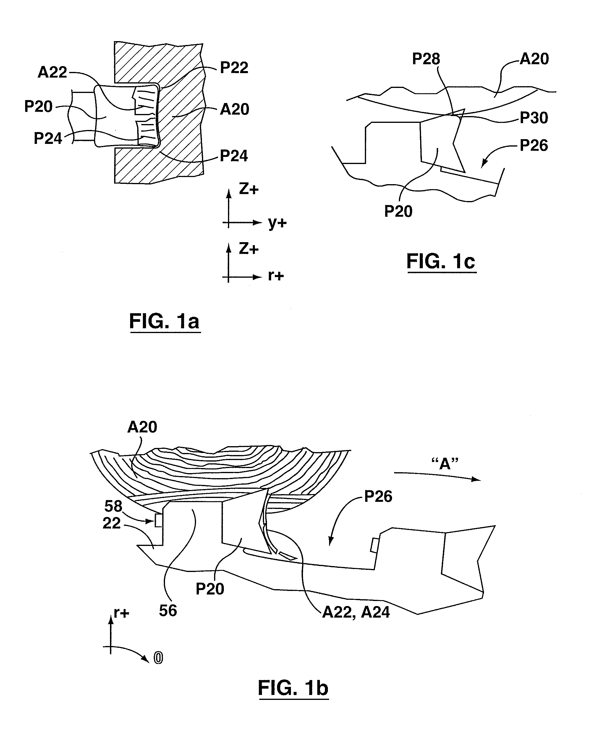
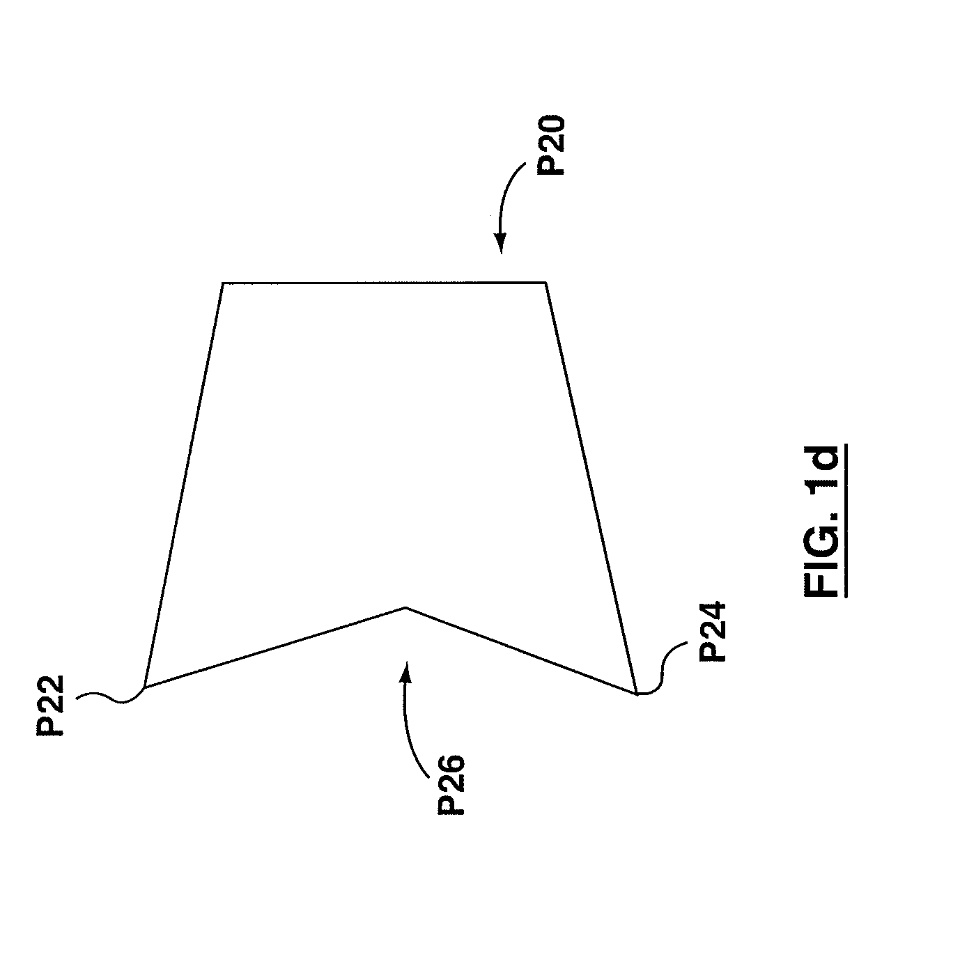
[0015]In another aspect of the invention there is a rotatable saw blade tooth for use on a forestry feller buncher saw blade. The tooth is mountable to a tooth seat of the saw blade. When mounted on the tooth seat, the tooth is movable in a direction of forward travel as the saw blade turns, so as to cut a tree. The saw blade tooth has a tooth body having a generally square pyramidal shape including a front end, a rear end, and first, second, third and fourth sides lying in respective first, second, third and fourth planes. The rear end has a mounting removably engageable with the tooth seat and rotatable about the direction of forward travel to a plurality of different seating orientations. Each of the first, second, third, and fourth sides is substantially trapezoidal in shape and tapers in width from the front end to the rear end. A first tip is formed at the meeting of the first and second sides and the front end. A second tip is formed at the meeting of the second and third sides and the front end. A third tip is formed at the meeting of the third and fourth sides and the front end. A fourth tip is formed at the meeting of the fourth and first sides and the front end. The front end is rearwardly sloped away from each of the first, second, third, and fourth tips. The tooth body has a central axis of symmetry extending longitudinally the direction of forward travel. A first transverse axis lies in a plane perpendicular to the first and third sides. A second transverse axis lies in a plane perpendicular to the second and fourth sides. The first and second transverse axes are perpendicular to the central axis of symmetry and define a cross-sectional plane of the tooth body. Each of the first, second, third, and fourth tips has an associated first, second, third and fourth region of local enlargement. The first region of local enlargement includes material that extends transversely proud of (i.e., beyond) the first and second planes.

Problems solved by technology

Saw teeth wear relatively quickly and may become rounded or dull.
This may cause increased fuel consumption, decreased productivity, or poor cut quality, or all of them, and may tend to result in a need for maintenance.
When cutting with a dull conventional saw tooth as described above, the narrower cutting tips cut an initial kerf and the thicker trailing tooth body has to be pushed through the initial kerf of the tree as the blade feeds through the tree, pushing and tearing the tree fiber above and below the initial kerf to create a wider final kerf equal to the width of the trailing tooth body thereby causing increased friction and loss of blade energy.
This may tend to consume more energy, decrease machine productivity and produce a rougher cut on the tree butt.
While these conventional saw teeth are easy to manufacture, as they wear the tend to become dull and rounded as described above.
The width of the leading cutting edge portion of the tooth body is worn thinner than the tooth body behind the leading edge causing increased friction, inefficient cutting and excessive loss of blade energy which results in more fuel being consumed.

Method used


Image

  • Saw tooth for circular saw
  • Saw tooth for circular saw
  • Saw tooth for circular saw

Examples


Embodiment Construction

[0044]The description that follows, and the embodiments described therein, are provided by way of illustration of an example, or examples of particular embodiments of the principles of the present invention. These examples are provided for the purposes of explanation, and not of limitation, of those principles and of the invention. In the description, like parts are marked throughout the specification and the drawings with the same respective reference numerals. The drawings are not necessarily to scale and in some instances proportions may have been exaggerated in order more clearly to depict certain features of the invention.

[0045]It may be helpful to identify co-ordinate systems that may aid in understanding the present invention. At the largest level, there may be a cylindrical polar co-ordinate system, in which the axial, or x-direction is defined by the axis of rotation of a feller buncher disc saw blade. The circumferential direction is that through which angles, angular velo...


PUM


Abstract

A tooth is provided for a circular disc felling saw. The saw tooth may have a generally square pyramidal shape with tips at each of the four corners. Each of the tips has an enlarged tip region where the tip is stepped outward from the adjacent sides. The front face of the tip remains smoothly continuous. The enlarged, or built-out region extends rearwardly a greater distance than the lateral step out distance, and the rearward build-out portion is relieved on planes parallel to the main portions of the planar sides of the pyramid. The tooth may have both leading and trailing cutting tips. Either one or both of the primary and secondary cutting tips may include a wear insert, such as a ceramic wear insert.

Description

[0001]This application claims the benefit of priority under 35 U.S.C. §119 of U.S. Provisional Patent Application Ser. No. 61 / 487,328 filed May 18, 2011, the specification and drawings of which are hereby incorporated by reference in their entirety.FIELD OF THE INVENTION[0002]The present invention relates to saw teeth for circular saws.BACKGROUND OF THE INVENTION[0003]Saw teeth for circular saws of the type mounted on a feller head for a tree felling apparatus are known. U.S. Pat. No. 4,932,447, Morin, 1990, and U.S. Pat. No. 5,205,199, MacLennan, 1993, represent saw teeth that have become well known in the industry. Morin '447 and MacLennan '199 both teach a replaceable saw tooth with four sides. The teeth can be rotated when the active cutting tips and edges become dull or worn.[0004]Saw teeth wear relatively quickly and may become rounded or dull. This may cause increased fuel consumption, decreased productivity, or poor cut quality, or all of them, and may tend to result in a ne...

Claims


Application Information

Patent Timeline
Patent Type & Authority Applications(United States)
IPC IPC(8): B27B33/02A01G23/091
CPCB27B33/08A01G23/091B27G13/10B02C18/182B23C5/202
Inventor MICACCHI, MAURICE
Owner MICACCHI MAURICE
Learn More