Methods And Systems For Generating Millimeter-Wave Oscillations

a millimeter-wave oscillation and millimeter-wave wave technology, applied in the direction of oscillator, antenna, semiconductor device, etc., can solve the problems of generating millimeter-wave signals that are ill-suited for several of these potential applications, gunn diodes are ill-suited for several of these applications, and the millimeter-wave signals were previously thought to be ill-suited, so as to achieve a large longitudinal component of an electric field and a large longitudinal componen

Active Publication Date: 2012-11-22
GEORGIA TECH RES CORP
View PDF1 Cites 13 Cited by
  • Summary
  • Abstract
  • Description
  • Claims
  • Application Information

AI Technical Summary

Benefits of technology

[0008]In accordance with one embodiment, a method for generating millimeter-wave oscillations comprises providing a semiconductor device comprising at least two terminals and a polar heterojunction formed from two semiconductor materials. The method further comprises applying a voltage bias to the terminals, the voltage biases being adapted to enhance a two-dimensional electron gas (2DEG) layer at the polar heterojunction and produce a sufficiently large longitudinal component of an electric field within the 2DEG. The produced longitudinal component of the electric field serves as a nucleation site for a plurality of propagating dipole domains observable as a plurality of self-sustaining millimeter-wave oscillations.
[0009]According to another embodiment, a method for generating millimeter-wave oscillations includes providing a semiconductor device comprising at least two terminals and a polar heterojunction formed from two semiconductor materials. The method further includes applying a first set of voltage biases to the terminals in a first mode and applying a second set of voltage biases to the terminals in a second mode. Further according to the method, the first voltage biases and the second voltage biases are adapted to enhance a two-dimensional electron ga...

Problems solved by technology

New areas of application have also where millimeter-wave signals were previously thought to be ill-suited due to their perceived susceptibility to atmospheric attenuation.
Presently known oscillators for generating millimeter-wave signals, however, are ill-suited for several of these potential applications.
Gunn diodes, although theorized for microwave through terahertz signal generation, are subject to severe tradeoffs ...

Method used


Image

  • Methods And Systems For Generating Millimeter-Wave Oscillations
  • Methods And Systems For Generating Millimeter-Wave Oscillations
  • Methods And Systems For Generating Millimeter-Wave Oscillations

Examples


examples

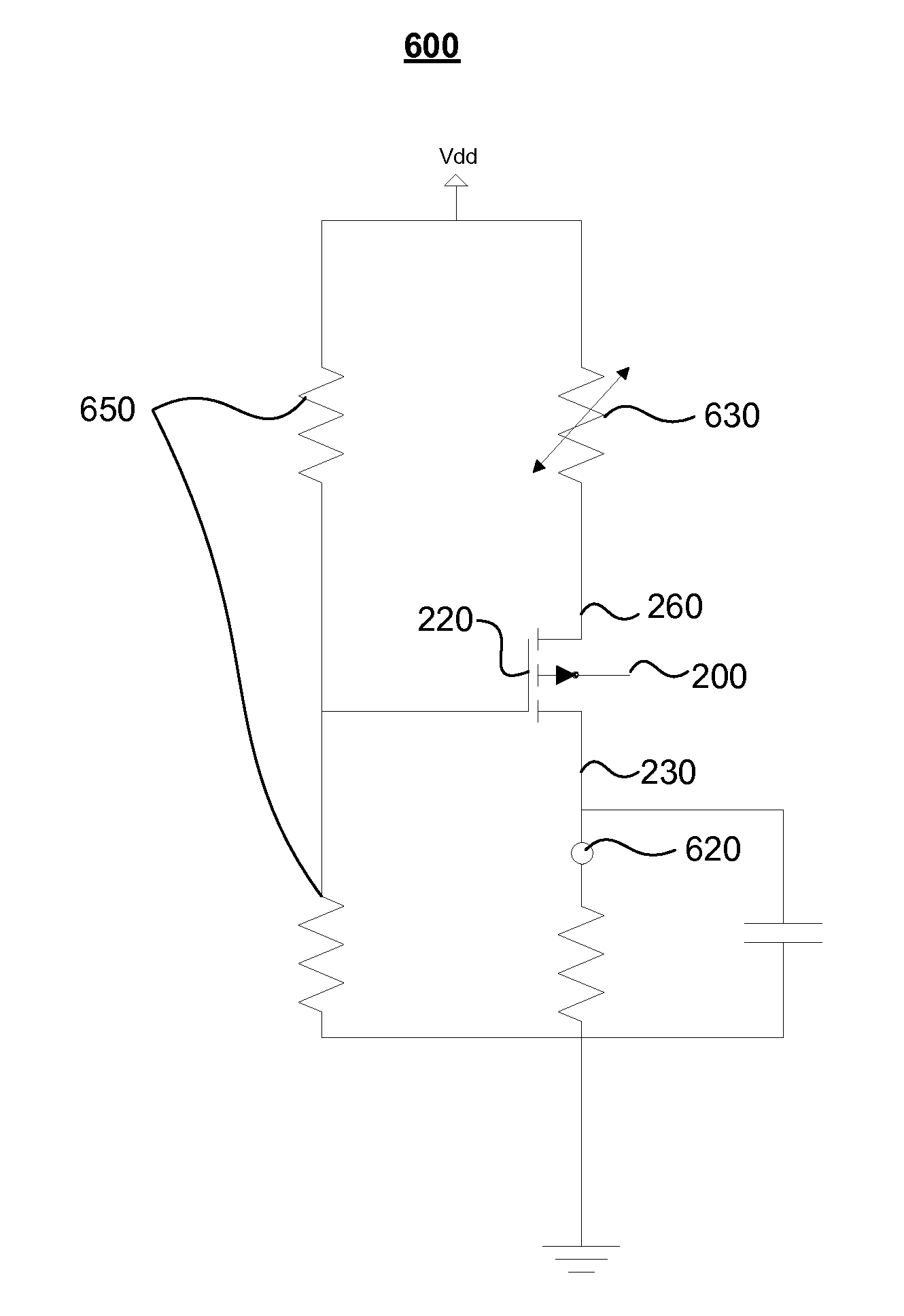
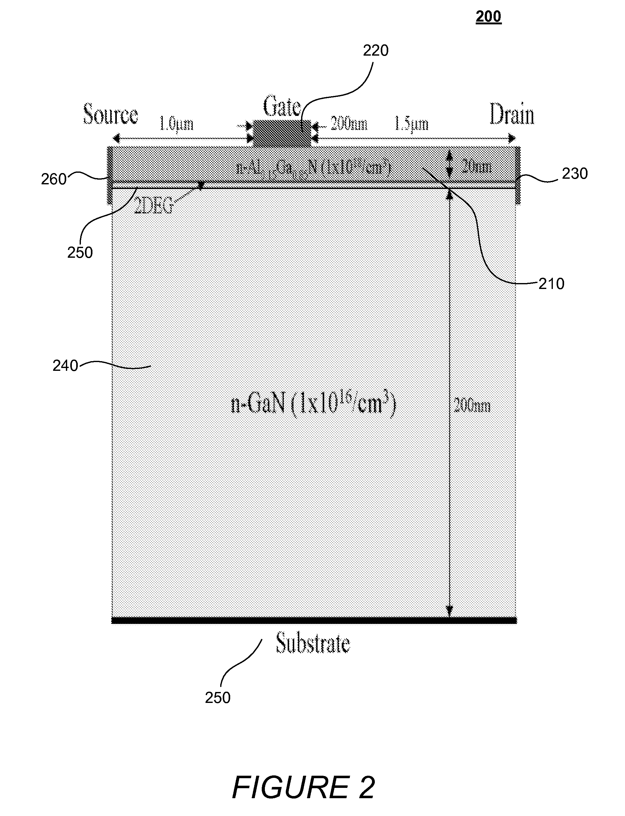
[0043]The following case was simulated using full-band ensemble Monte Carlo simulation to study the microscopic operation of an example device, as describe herein in reference to FIG. 2. The exemplary device depicted in the two-dimensional, cross-sectional illustration of FIG. 2 includes source (cathode), drain (anode), and gate (control) electrodes. The former two contacts, in contrast to the gate electrode, are Ohmic. A relatively large gate bias served to further increase sheet electron density in the 2DEG below the gate. Through the phenomenon of field crowding, the gate electrode induced an additional large gradient in the longitudinal component of electric field at the 2DEG interface, which facilitated the initiation and launching of traveling domains towards the anode.

[0044]The simulation revealed two modes of operation. A traveling depletion-layer domain was observed under a gate bias of 2V and a drain-source bias of 50V. In this mode of operation, the channel supported one ...


PUM


Abstract

The various embodiments of the present invention provide improved methods and circuits for generating millimeter-wave oscillations. Generating millimeter-wave oscillations may involve providing a semiconductor device comprising at least two terminals and a polar heterojunction formed from two semiconductor materials. A voltage bias may be applied to at least two terminals of the device in which the voltage enhances a two-dimensional electron gas (2DEG) layer at the polar heterojunction and produces a sharply-peaked but spatially-localized electric field within the 2DEG with a large longitudinal component, wherein the longitudinal component of the electric field serves as a nucleation site for a plurality of propagating dipole domains observable as a plurality of self-sustaining millimeter-wave oscillations.

Description

CROSS-REFERENCE TO RELATED APPLICATIONS[0001]This application claims the benefit of U.S. Provisional Patent Application Ser. No. 61 / 299,440, filed 29 Jan. 2010, which is incorporated herein by reference in its entirety as if fully set forth below.TECHNICAL FIELD[0002]The present invention relates generally to methods and systems for generating high-frequency oscillations, and more particularly to methods and systems for generating millimeter-wave and terahertz oscillations using a semiconductor device.BACKGROUND[0003]Millimeter-wave signals increasingly find application in various fields and applications. In the telecommunications arena, for example, the United States has designated certain frequency bands in the millimeter-wave band for areas of future expansion. For example, the 38.6-40.0 GHz band has been chosen for licensed high-speed microwave data links, which experimental systems have shown capable of 10-Mbit / s over a microwave data link. Additionally, the 60 GHz band has bee...

Claims


Application Information

Patent Timeline
IPC IPC(8): H03B5/24
CPCH01Q1/38H01Q9/285H03B9/12H03B2200/0084H01L29/778
Inventor YODER, PAUL DOUGLASSRIDHARAN, SRIRAAMAN
Owner GEORGIA TECH RES CORP
Why Eureka
Try Eureka