Filter and duplexer

a filter and duplexer technology, applied in the direction of piezoelectric/electrostrictive/magnetostrictive devices, electrical apparatus, impedence networks, etc., can solve problems such as enlarged loss

Active Publication Date: 2012-11-29
TAIYO YUDEN KK
View PDF2 Cites 15 Cited by
  • Summary
  • Abstract
  • Description
  • Claims
  • Application Information

AI Technical Summary

Benefits of technology

[0008]According to another aspect of the present invention, there is provided a duplexer including: a first filter coupled between a common terminal and a first terminal; and a second filter that is coupled between the common terminal and a second terminal and has a pass band higher than that of the first filter, the first filter having one or a plurality of parallel resonators coupled between an inputting terminal and an outputting terminal in parallel, and one or a plurality of film bulk acoustic resonators that acts as a series resonator and is coupled between the inputting terminal and the outputting terminal in series, the film bulk acoustic resonator having a substrate, a lower electrode provided on the substrate, a piezoelectric membrane provided on the lower electrode, and an upper electrode provided on the piezoelectric membrane, wherein: at least one of the lower electrode and the upper electrode has a thick membrane region having a thickness larger than that of a center portion of a resonance region at an edge of the resonance region, the resonance region being a region where the lower electrode and the upper electrode face with each other through the piezoelectric membrane; and a width of the thick membrane region is smaller than a wavelength of an acoustic wave propagating in a direction crossing a thickness direction of the piezoelectric membrane.

Problems solved by technology

However, with the method of Document 1, loss may be enlarged.

Method used


Image

  • Filter and duplexer
  • Filter and duplexer
  • Filter and duplexer

Examples


first embodiment

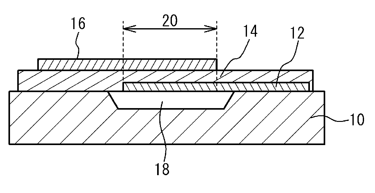
[0069]FIG. 16 illustrates a calculation result of a dispersion curve of AlN. A horizontal axis of FIG. 16 indicates a wave number. A vertical axis of FIG. 16 indicates a frequency. The dispersion curve is calculated under a condition that the lower electrode 12 is a molybdenum membrane having a thickness of 350 nm, the upper electrode 16 is a molybdenum membrane having a thickness of 300 nm, and the piezoelectric membrane 14 is an AlN membrane having a thickness of 1050 nm.

[0070]In FIG. 16, a mode TE is a thickness longitudinal vibration mode. A mode TS is a thickness lateral vibration mode. A solid line indicated by the mode TE1 is a main mode for a function as a film bulk acoustic resonator. The wave number of the main mode TE1 is an ideal number. A region in which a frequency is reduced together with the wave number is a region (a broken line region of TE1 of FIG. 16) in which a spurious is generated. Here, in FIG. 16, a low order vibration mode TE0 (illustrated with a broken lin...

second embodiment

[0093]In FIG. 19 and FIG. 20A, the loss of the first embodiment is smaller than that of the third comparative example. However, the restraint degree of the spurious of the first embodiment is not larger than that of the third comparative example. It is thought this is because there does not exist a region, in which a wave number is an imaginary number, at the edge of the resonance region 20 restraining the spurious. The mode TE0 is a mode without the cutoff frequency. Therefore, it is difficult to form a region, in which a wave number is an imaginary number, outside of the resonance region by forming a thin membrane region or a thick membrane region in the upper electrode 16.

[0094]FIG. 22A and FIG. 22B illustrate a cross sectional view of a film bulk acoustic resonator in accordance with the second embodiment. As illustrated in FIG. 22A, the thickness of the piezoelectric membrane 14 is smaller than that of the resonance region 20 in a region 34 outside of the thick membrane region ...

third embodiment

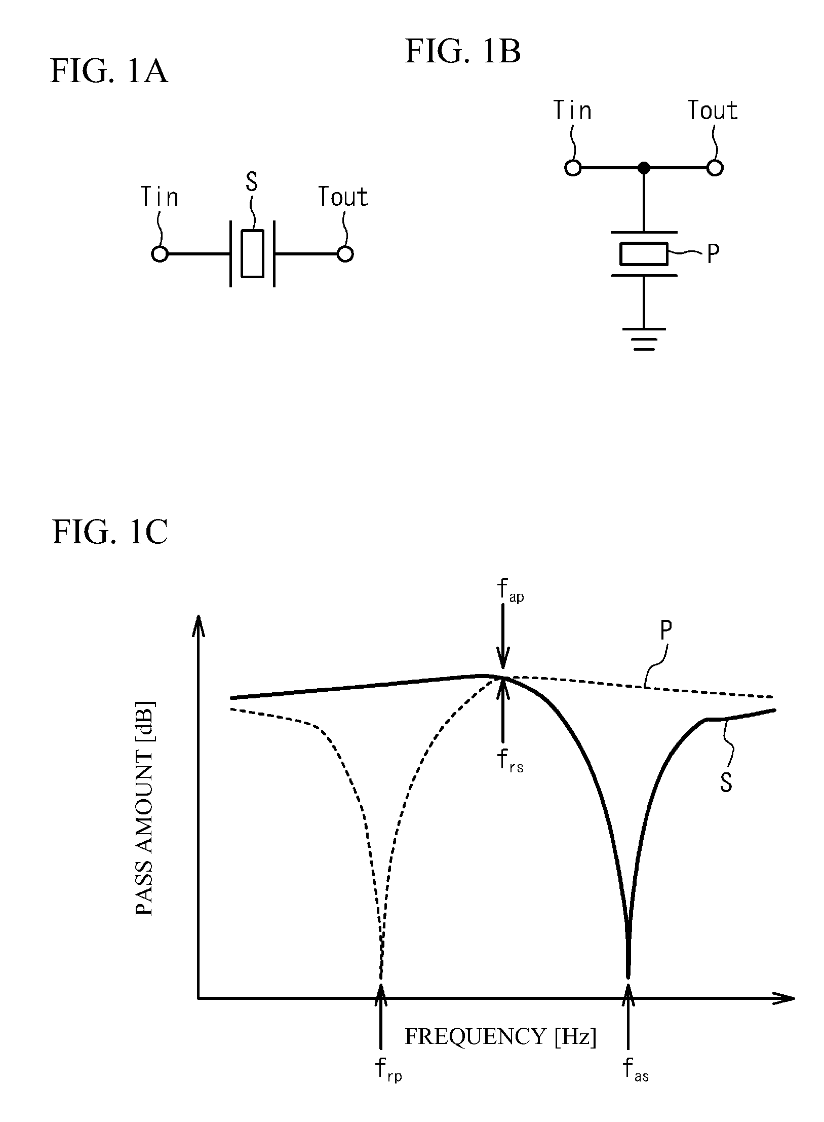
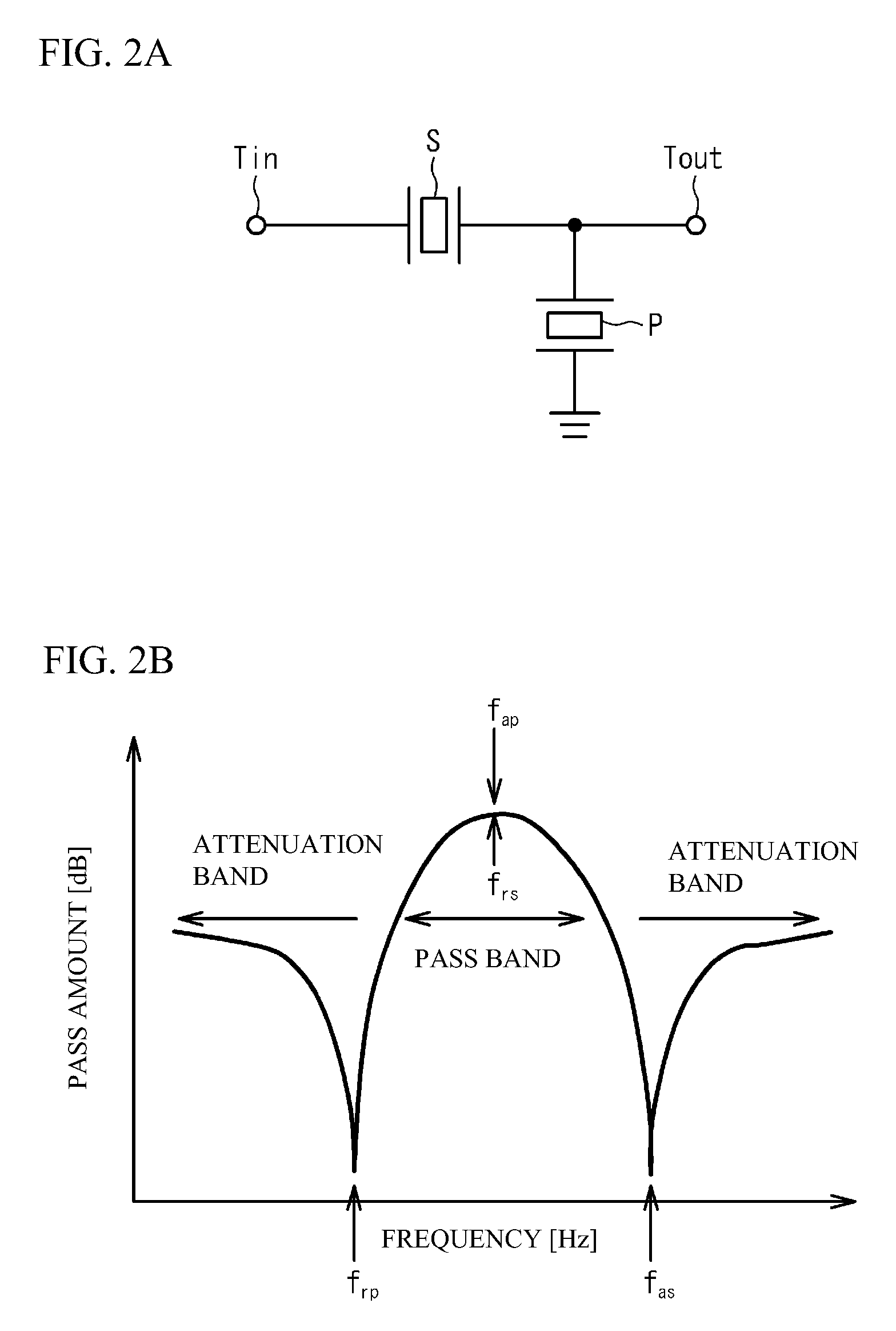
[0097]A third embodiment is an example of using the film bulk acoustic resonators in accordance with the first embodiment and the second embodiment as a ladder type filter. FIG. 23 illustrates a circuit diagram of a ladder type filter in accordance with the third embodiment. As illustrated in FIG. 23, the ladder type filter has one or a plurality of series resonators S1 to S3 and one or a plurality of parallel resonators P1 and P2. The one or the plurality of the series resonators S1 to S3 are coupled in series between the inputting terminal Tin and the outputting terminal Tout. The one or the plurality of the parallel resonators P1 and P2 are coupled in parallel between the inputting terminal Tin and the outputting terminal Tout.

[0098]When a spurious is generated at a frequency lower than the resonance frequency as illustrated in FIG. 5B and is generated in the series resonator S as illustrated in FIG. 2B, a ripple may be generated in a pass band. On the other hand, even if a spuri...


PUM


Abstract

A filter includes one or a plurality of parallel resonators coupled in parallel and one or a plurality of a film bulk acoustic resonators coupled in series, the film bulk acoustic resonator having a substrate, a lower electrode, a piezoelectric membrane, and an upper electrode, wherein: at least one of the lower electrode and the upper electrode has a thick membrane region having a thickness larger than that of a center portion of a resonance region at an edge of the resonance region, the resonance region being a region where the lower electrode and the upper electrode face with each other through the piezoelectric membrane; and a width of the thick membrane region is smaller than a wavelength of an acoustic wave propagating in a direction crossing a thickness direction of the piezoelectric membrane.

Description

CROSS-REFERENCE TO RELATED APPLICATION[0001]This application is based upon and claims the benefit of priority of the prior Japanese Patent Application No. 2011-116357, filed on May 24, 2011, the entire contents of which are incorporated herein by reference.FIELD[0002]A certain aspect of the present invention relates to a filter and a duplexer, an in particular, relates to a filter and a duplexer having a thick membrane region at an edge of a resonance region.BACKGROUND[0003]A demand for a high frequency filter is rapidly enhanced because a wireless communication device such as a mobile phone is rapidly spread. In particular, an acoustic wave filter having a small size and having high precipitousness is demanded. The acoustic wave filter has an acoustic wave resonator. For example, in a high frequency band higher than 2 GHz band, a film bulk acoustic resonator is focused as a resonator having a small size and small loss. The film bulk acoustic resonator has a lower electrode, an uppe...

Claims


Application Information

Patent Timeline
Patent Type & Authority Applications(United States)
IPC IPC(8): H03H9/70H03H9/58
CPCH03H9/0211H03H9/02118H03H9/706H03H9/171H03H9/02157
Inventor HARA, MOTOAKITSUTSUMI, JUN
Owner TAIYO YUDEN KK
Why Eureka
Try Eureka