[0008]This object is achieved according to the invention by virtue of the fact that the piston of the respective compressor stage is connected with a
liquid column of an incompressible liquid situated in the compressor cylinder, which converts the piston
stroke motion of the piston into a motion of a compressor piston arranged in the compressor cylinder so that it can longitudinally shift, wherein the
liquid column for changing the compressor
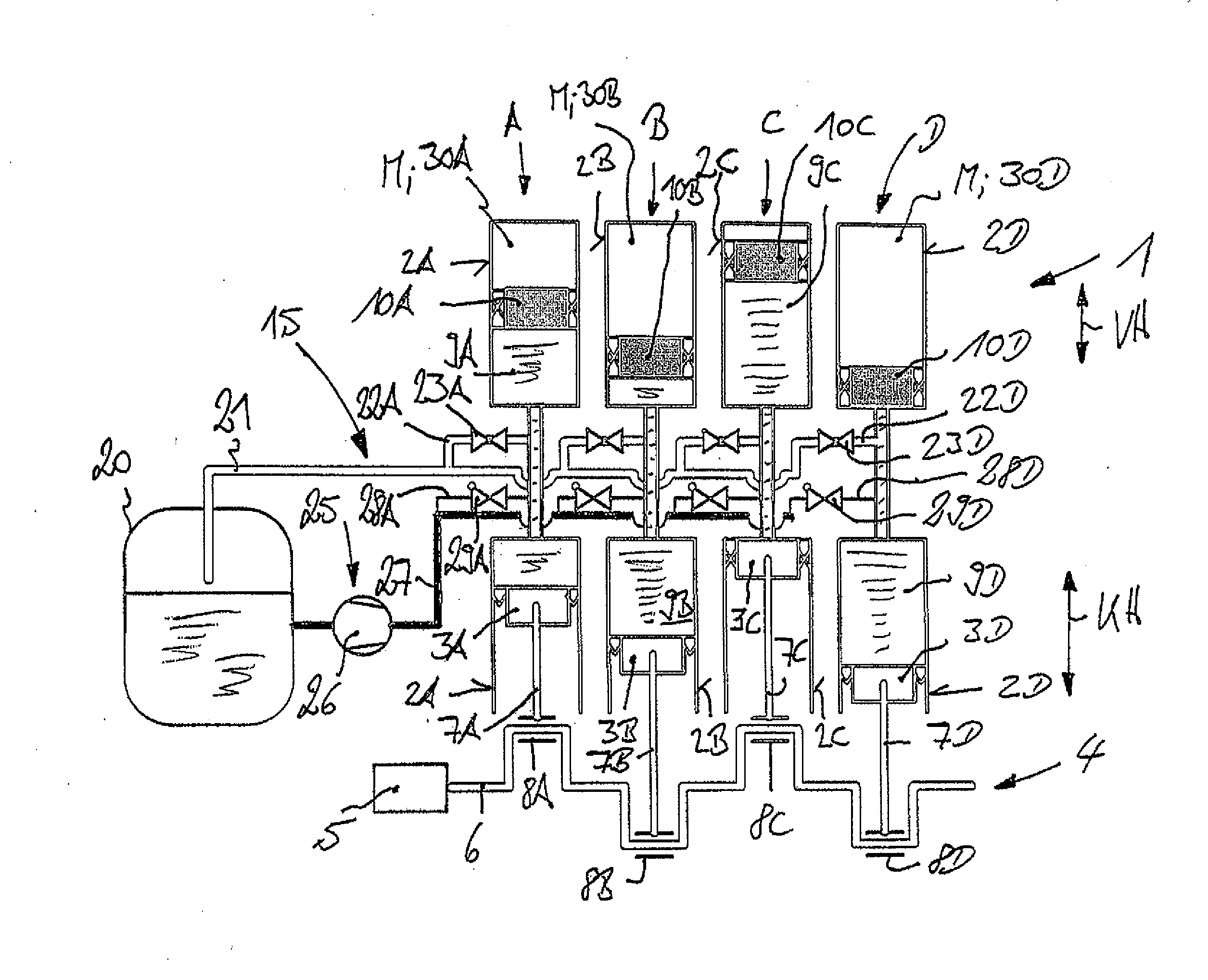
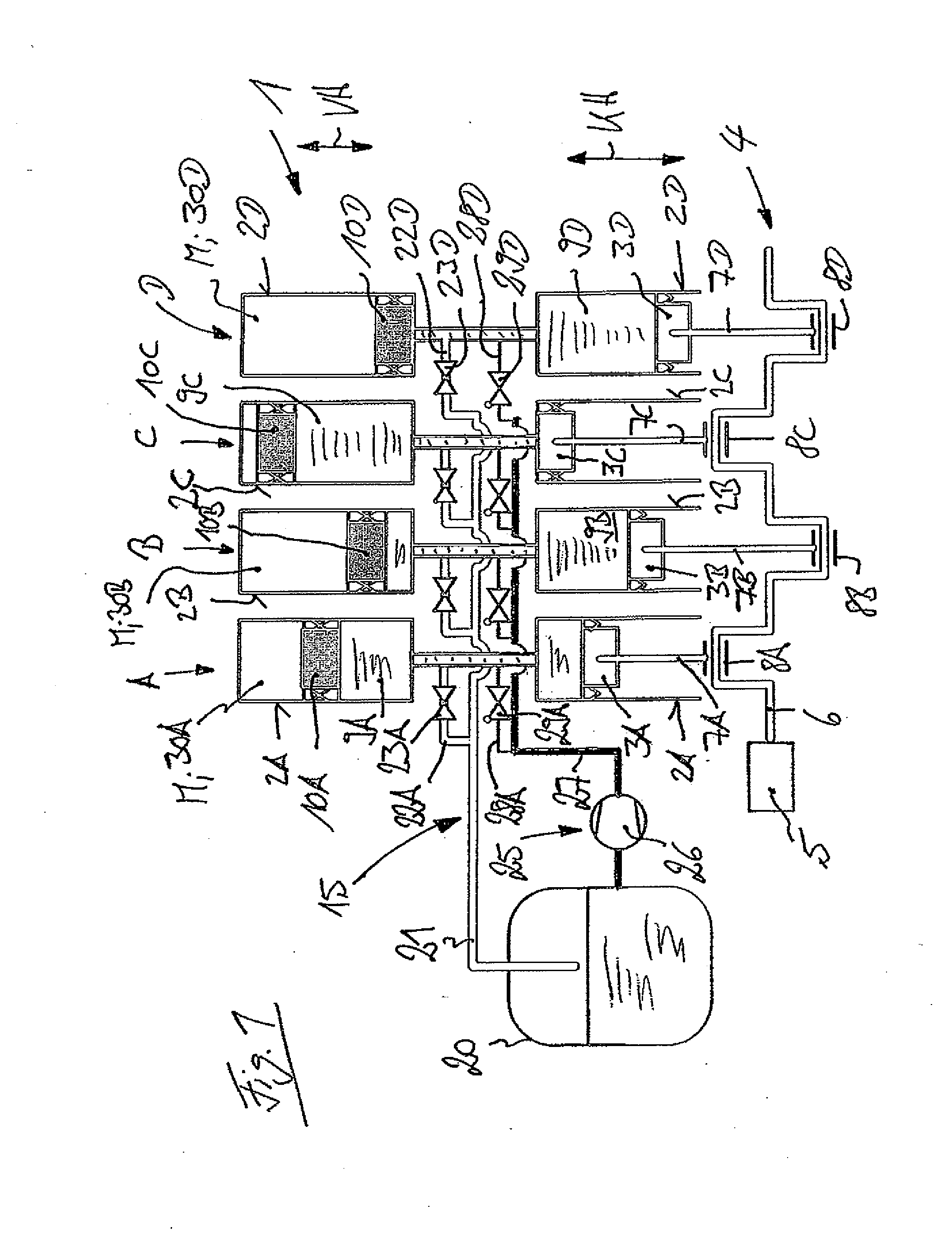
stroke of the compressor piston can be connected with an outlet. According to the invention, the piston of each compressor stage mechanically coupled with the drive train is hence connected by way of a
liquid column of an incompressible liquid, for example a
hydraulic fluid, with a compressor piston, which executes the corresponding compressor stroke for compressing the medium to be compressed. The liquid column of each compressor stage can be altered and varied in a manner according to the invention by connecting the liquid column with an outlet, so that given a constant piston stroke of the piston mechanically powered by the drive train, the compressor stroke of the compressor piston allocated to the piston can be controlled independently of the piston stroke. This makes it possible to partially or completely deactivate a compressor piston even though the piston is powered, and thereby
shut down and immobilize the compressor piston or control it in the compressor stroke. In the multistage piston compressor according to the invention, independent and individually operable compressor stages can hence be achieved given a shared drive train. As a consequence, connecting the liquid column of
hydraulic fluid powered by the piston according to the invention readily enables a partial load operation of a corresponding compressor stage. In addition, connecting the liquid column with an outlet makes it possible to deactivate one or more compressor stages, in which the corresponding compressor pistons have been immobilized and
shut down, and do not perform any motions in the compressor cylinders. Shutting down or varying the compressor stroke of the corresponding compressor pistons leads to improved energy efficiency, since no drive power needs to be applied for the deactivated piston, or changing the corresponding compressor stroke of the compressor piston places a uniform load on the drive train in a partial load range. In addition, shutting down the compressor piston reduces or avoids
mechanical wear on the surfaces between the pistons and compressor cylinders, the seals of the piston, and the inlet and outlet valve of the medium of a no-load compressor stage.
[0009]In a preferred embodiment of the invention, a valve arrangement is provided for connecting the liquid column with the outlet. A corresponding valve arrangement can be used to easily control the process of connecting the liquid column powered by the piston drivingly linked with the drive train with the outlet, so that the valve arrangement conveys the liquid column powered by the piston to the outlet, so as to partially or completely deactivate the compressor cylinder allocated to the piston.

