Plasma-resistant member

a technology of yttria and member, applied in the field of plasma-resistant member, can solve the problem of cracking at the interface between the thin film of yttria and the component member

Active Publication Date: 2012-11-29
NGK INSULATORS LTD
View PDF1 Cites 4 Cited by
  • Summary
  • Abstract
  • Description
  • Claims
  • Application Information

AI Technical Summary

Benefits of technology

[0007]The present invention has been accomplished to solve such a problem. A main object of the present invention is to suppress occurrence of cracks at the interface between the thin film and the base member after a temperature increase to 700° C.
[0009]The present invention provides an advantage that cracks are not occurred at the interface between the thin film and the base member after a temperature increase to 700° C. In particular, when a ratio a2 / a1 satisfies 1.17≦a2 / a1≦1.50, this advantage can be provided with certainty.

Problems solved by technology

However, when a base member formed of a silicon nitride sintered body, an aluminum nitride sintered body, an alumina sintered body, or a silicon carbide sintered body is used as a component member, a temperature increase to 700° C. sometimes causes cracks at the interface between the yttria thin film and the component member.

Method used


Image

  • Plasma-resistant member
  • Plasma-resistant member

Examples


experimental example 1

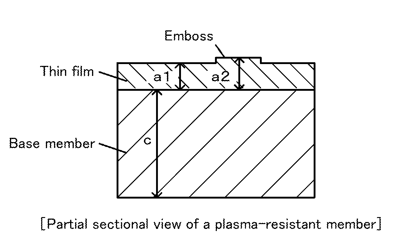
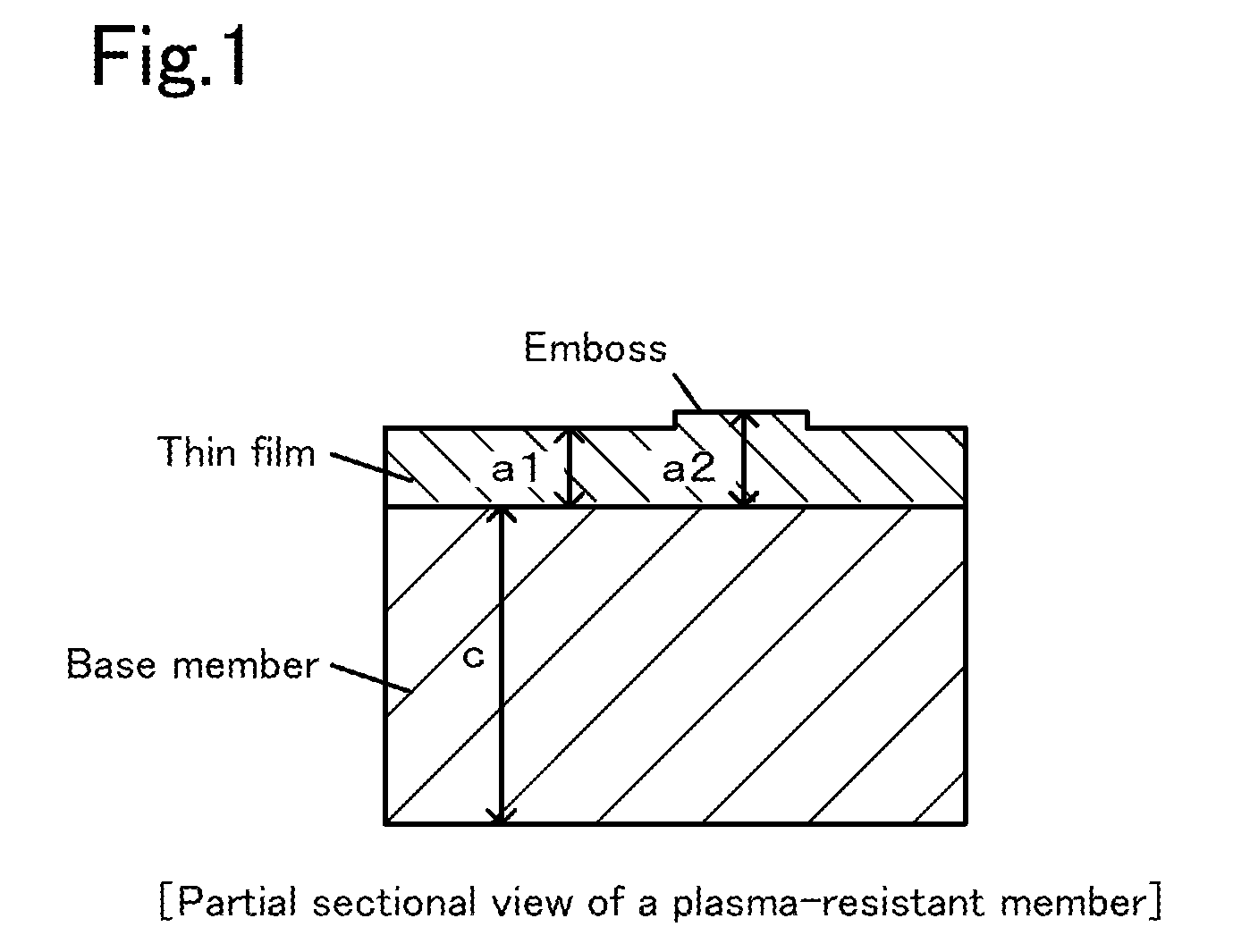
[0019]Plasma-resistant members of six types in which an yttria thin film was formed on a surface of a base member formed of an aluminum nitride sinter were produced in the following manner.

[0020]An aluminum nitride sinter having a diameter of 350 mm and an average thickness of 20 mm was first produced. Specifically, an yttria powder having an average particle size of 1.5 μm and a purity of 99.9% was added in an amount of 5% by weight to an aluminum nitride powder having an average particle size of 1 μm and a purity of 99.9%. These powders were mixed and the powder mixture was uniaxially press-formed at 100 kgf / cm2. This formed body was sintered by a hot-press process. Thus, the aluminum nitride sintered body was obtained.

[0021]Yttria having a purity of 99.9% by weight was then thermally sprayed to the entire surface of the aluminum nitride sintered body. As a result, an aluminum nitride sintered body the entire surface of which was covered with the yttria thermal-spraying film was o...

experimental example 2

[0024]Plasma-resistant members of four types in which a YAG thin film was formed on a surface of a base member formed of a silicon nitride sintered body were produced (diameter of embossed portions: 2.0 mm). Table 2 describes details of the plasma-resistant members having Experiment Nos. 2-1 to 2-4. Each of the plasma-resistant members was subjected to a temperature increase to 700° C. in the air and, after the temperature increase, it was inspected whether cracks were occurred at the interface between the silicon nitride sintered body and the YAG thin film or not. It was found that cracks were occurred in the members in which the ratio a2 / a1 was 1.6 or more, whereas cracks were not occurred in the members in which the ratio was 1.5 or less. Experiment Nos. 2-3 and 2-4 correspond to Examples of the present invention; and Experiment Nos. 2-1 and 2-2 correspond to Comparative examples for the present invention.

TABLE 2Thin film (Thermal-spraying film)Base memberFilm thicknessHeight ofA...


PUM

PropertyMeasurementUnit
temperatureaaaaaaaaaa
thicknessaaaaaaaaaa
thicknessaaaaaaaaaa

Abstract

A plasma-resistant member according to the present invention includes a base member formed of a silicon nitride sintered body, an aluminum nitride sintered body, an alumina sintered body, or a silicon carbide sintered body; and a thin film formed on a surface of the base member and composed of an yttrium compound or a spinel, wherein the thin film has, in a surface of the thin film, a plurality of projections for supporting a wafer, and a ratio a2 / a1 of a film thickness a2 of portions of the thin film that include the projections to a film thickness a1 of portions of the thin film that do not include the projections satisfies 1<a2 / a1<1.6.

Description

BACKGROUND OF THE INVENTION[0001]1. Field of the Invention[0002]The present invention relates to a plasma-resistant member.[0003]2. Description of the Related Art[0004]A plasma-resistant member is known in which an aluminum nitride sintered body is used as a base member and, in the base member, an yttria thin film is formed on a surface to be exposed to plasma (for example, Patent Literature 1).CITATION LISTPatent Literature[0005][PTL 1] Japanese Unexamined Patent Application Publication No. 2000-129388SUMMARY OF THE INVENTION[0006]However, when a base member formed of a silicon nitride sintered body, an aluminum nitride sintered body, an alumina sintered body, or a silicon carbide sintered body is used as a component member, a temperature increase to 700° C. sometimes causes cracks at the interface between the yttria thin film and the component member.[0007]The present invention has been accomplished to solve such a problem. A main object of the present invention is to suppress occ...

Claims


Application Information

Patent Timeline
Patent Type & Authority Applications(United States)
IPC IPC(8): B32B3/30
CPCC04B41/87Y10T428/24355C04B41/5032C04B41/5045C04B41/009Y10T428/24479Y10T428/24612C22C29/16C22C29/12C22C29/065C04B35/10C04B35/565C04B35/581C04B35/584C04B41/4527
Inventor GOTO, YOSHINOBU
Owner NGK INSULATORS LTD
Why Eureka
Try Eureka