Stent

a technology of stents and stents, applied in the field of medical implants, can solve the problems of clinically significant narrowing of arteries, increased size and thickness, or even complete occlusion, and achieve the effects of reducing profile, reducing profile, and reducing profil

Active Publication Date: 2012-11-29
WL GORE & ASSOC INC
View PDF5 Cites 87 Cited by
  • Summary
  • Abstract
  • Description
  • Claims
  • Application Information

AI Technical Summary

Benefits of technology

[0006]Another exemplary device is a stent having distal and proximal ends, and defining a central lumen along a longitudinal axis. The stent has an insertion configuration with a reduced profile and a deployed configuration with an enlarged profile greater than the reduced profile. The stent has several portions. To define a closed cell structure, the stent has a plurality of spaced apart, undulating circumferential members with one undulating helical turn and one or more undulating circumferential rings. To define an open cell structure, the stent also has a helical element extending along the longitudinal axis axially interposed between the undulating circumferential members with a plurality of helical turns. The undulating helical turn of the circumferential member is directly connected to the helical body. Together, the undulating helical turn and the helical body defined a uniform apex geometry.
[0007]Another e...

Problems solved by technology

Over time, the plaque can increase in size and thickness and can eventually ...

Method used


Image

  • Stent
  • Stent
  • Stent

Examples


example 1

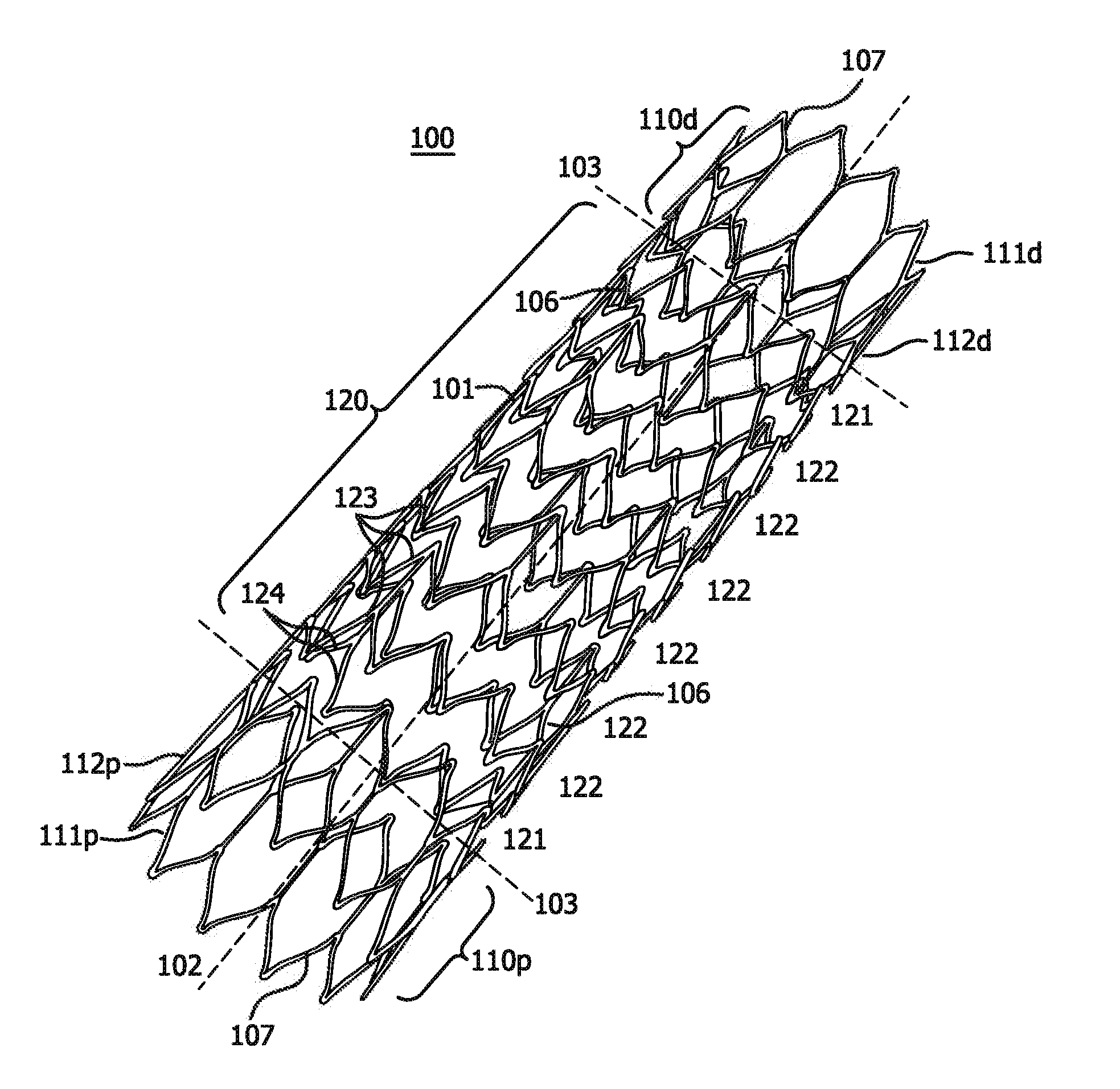
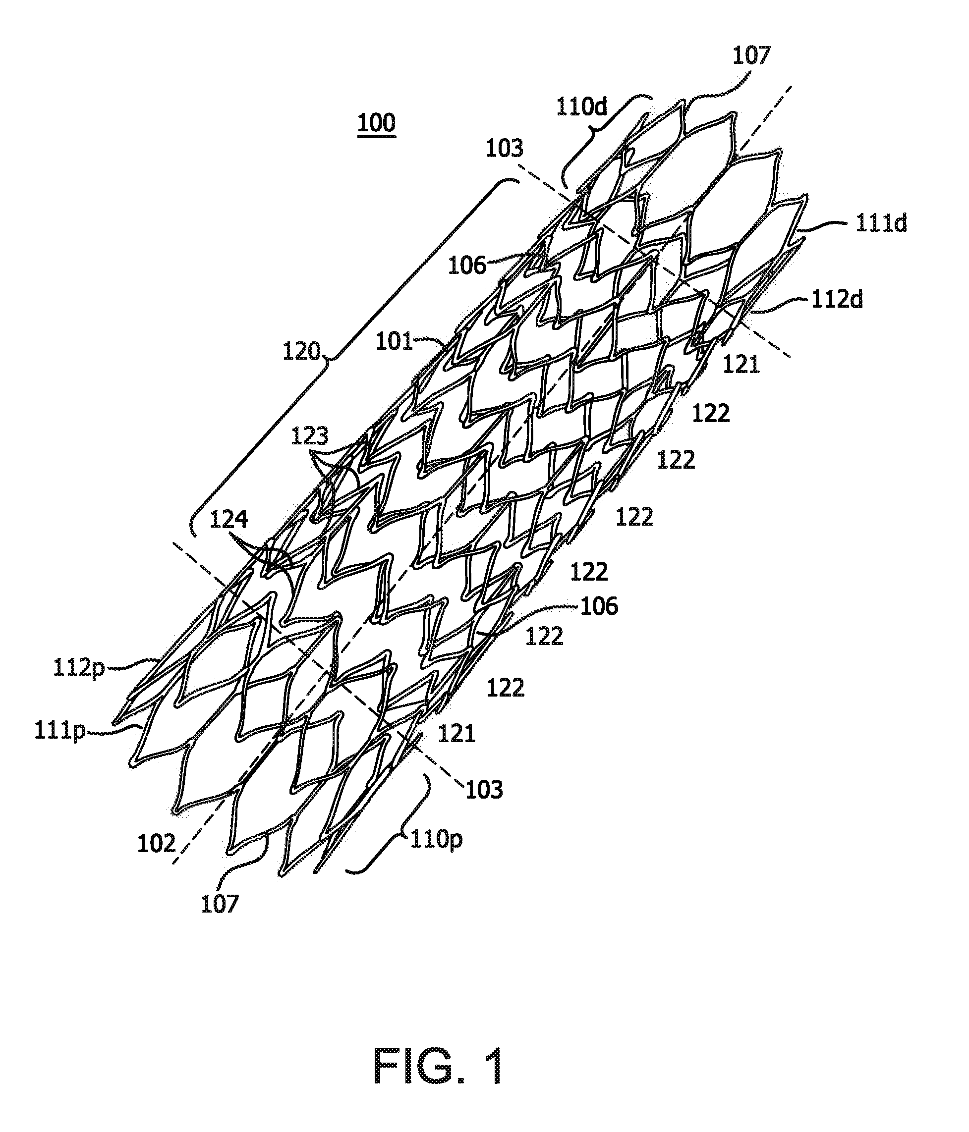
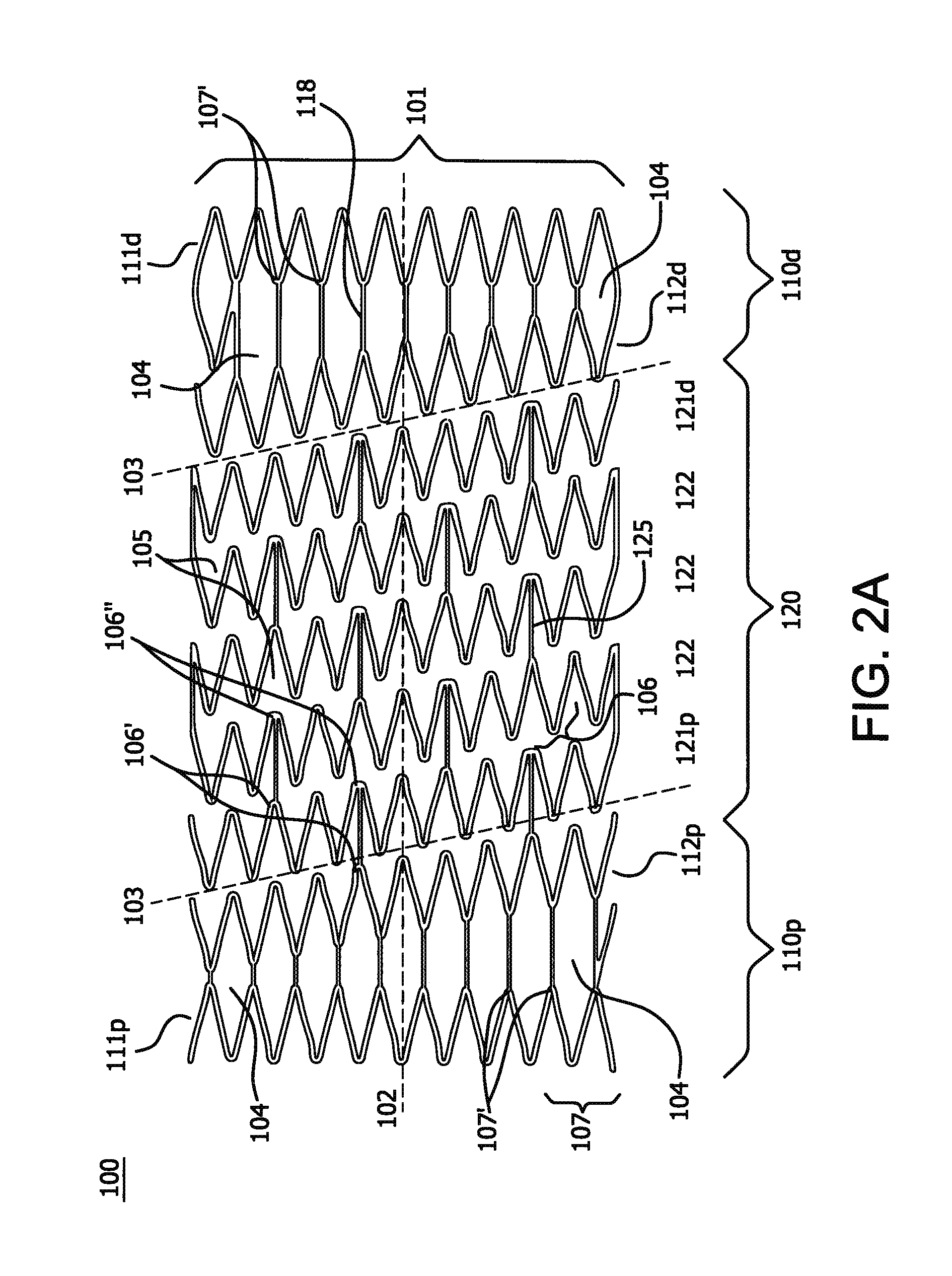
[0136]A stent is prepared using a commercially-available medical grade nitinol tubing. The composition of the nitinol is selected so that the finished stent frame, prior to subsequent processing as described in examples 5 and 6 below, has an active austenitic transformation finish temperature of about 20° C. or less. The tubing is laser cut to remove material from the tubing and to provide a structure as shown in FIGS. 2A and 2B with 10 apices and a deployed diameter of about 8 mm, a thickness of about 0.15 mm. Slag, which can be formed during laser cutting of nitinol, is removed by mechanical or chemical techniques to provide a smooth exterior surface. The laser cut tube also is electropolished.

[0137]This self-expanding stent device is diametrically compacted at ambient temperature. Compaction is effected using a collet or iris type of diametrical compaction device, such as taught by U.S. Pat. No. 6,629,350. The compacted stent device is inserted directly from the compaction device...

example 2

[0138]The stent with 11 apices and 10 mm deployed diameter prepared in accordance with a configuration illustrated in FIGS. 6A and 6B and substantially as set forth in Example 1. This time, however, the self-expanding stent device is diametrically compacted at a reduced temperature of about −10° C.

example 3

[0139]A lattice of the type shown in FIGS. 7A and 8B with square-shaped openings is prepared. A mandrel is wrapped with an ePTFE film with a discontinuous FEP coating to a thickness of approximately 0.05 mm. The film-mandrel assembly is placed into an oven at 320° C. for 12 minutes to bond the layers. The assembly is removed from the oven and allowed to cool at room temperature to provide an ePTFE tube. Using a CO2 laser, a pattern of regular square openings is cut into the tube. The openings are square-shaped with a size of less than about 0.5 mm. The width of the lattice segments is greater than about 0.05 mm (see FIG. 7B). The prepared square shaped lattice is placed in a convection oven set at 370° C. for 12 minutes. The material shrinks during heating to form squares that are approximately 0.5 mm diameter inscribed circle and lattice segments that are approximately 0.05 mm wide.


PUM


Abstract

The invention relates to a medical device and a method of using it. The device is a stent which can be percutaneously deliverable with (or on) an endovascular catheter or via other surgical or other techniques and then expanded. The stent is configured to have a central portion defined by “open” cells and at least two end portions, defined by “closed” cells, spaced apart and directly connected to the distal and proximal ends of the central portion of the stent. The stent may also optionally have a covering or a lattice with openings.

Description

CROSS-REFERENCE TO A RELATED APPLICATION[0001]This application claims the priority benefit under 35 U.S.C. §119(e) of U.S. Provisional Application No. 61 / 433,069 filed on Jan. 14, 2011 and U.S. Provisional Application No. 61 / 523,115 filed on Aug. 12, 2011, the content of which is incorporated herein in its entirety.FIELD OF THE INVENTION[0002]The invention relates generally to medical implants for supporting, maintaining, or repairing a lumen, passageway or opening in a living body and to methods of using them. In particular, the invention relates to medical devices that are designed to be inserted endoluminally into a body.BACKGROUND OF THE INVENTION[0003]Medical stents are generally known. One use for medical stents is to expand a body lumen, such as a blood vessel, which has contracted in diameter through, for example, the effects of lesions called atheroma or the occurrence of cancerous tumors. Atheroma refers to lesions within arteries that include plaque accumulations that can...

Claims


Application Information

Patent Timeline
IPC IPC(8): A61F2/82A61F2/07A61F2/915A61F2/958A61F2/966
CPCA61F2/07A61F2/915A61F2/966A61F2002/91558A61F2002/91575A61F2220/0075A61F2/88A61F2002/075A61F2230/0054A61F2220/005A61F2002/9583A61F2/844A61F2/90A61F2/82A61F2002/9155A61F2250/0036A61F2250/0029
Inventor ARMSTRONG, JOSEPH R.CULLY, EDWARD H.FRANKLIN, MICHAEL W.HANSEN, MARK Y.LURIE, BRANDON A.MCMURRAY, CRAIG R.MONTGOMERY, WILLIAM D.TERRY, WENDY J.TITTELBAUGH, ERIC M.
Owner WL GORE & ASSOC INC
Why Eureka
Try Eureka