Architectured reinforcement structure

a technology of reinforced concrete and reinforced structure, applied in the direction of buildings, buildings, constructions, etc., can solve the problems of inability to achieve the accuracy and standards of steel construction, inability to accurately measure the thickness of protective layer, and poor structural stability of concrete construction, so as to improve the ability of beam-column joint, reduce the effect of hive, segregation and bleeding

Inactive Publication Date: 2012-12-06
NAT TAIWAN UNIV OF SCI & TECH
View PDF8 Cites 58 Cited by
  • Summary
  • Abstract
  • Description
  • Claims
  • Application Information

AI Technical Summary

Benefits of technology

[0013]Accordingly, by implementing the architectured reinforcement structure of the present invention, the construction of the concrete structure reinforced by steel frame can be improved, and the connection of the beams and columns can have advantages as follows:
[0014]The grouting and tamping of concrete construction is improved, and the phenomena such as hive, segregation, and bleeding can be reduced.
[0015]The ability of beam-column joint is improved, for example, the ability of confinement is improved.
[0017]In addition to better ensure the structural safety, but also saves manpower and schedule.

Problems solved by technology

Before concrete grouting, safety supports are required to sustain the steel structure, thus leads to a messy construction site and steel construction can not achieve the accuracy and standards.
And it is often result in inaccuracy of protective layer thickness, lack of reinforcement spacing, or short of numbers of stirrups in joints, and such defects usually cause failure after the earthquake occurred.
The reinforcement without bonding strength often buckles and fails when encountering ultimate strength limitation.
The core concrete cannot be confined and extend the cross-sectional strength, thus results in brittle damage.
Unlike general building materials, those particular structural steel design lack practicability and progressiveness.
Particular structural steel or building materials of particular shapes are not for widespread use.
The size of a particular design or manufacture of building materials required to open an individual molds, resulting in increase of the overall costs.
Therefore once the production is delayed, it will affect the construction progress.
And once the production is over the requirement, it will cause the waste of discarded building materials.
It may seriously affect the quality of construction and completion on schedule.

Method used


Image

  • Architectured reinforcement structure
  • Architectured reinforcement structure
  • Architectured reinforcement structure

Examples


Embodiment Construction

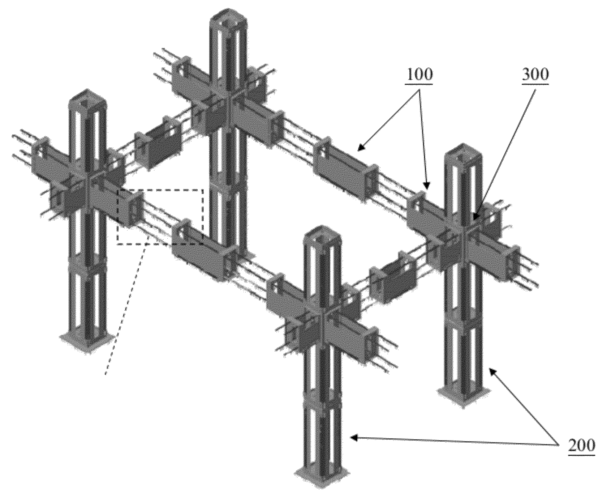
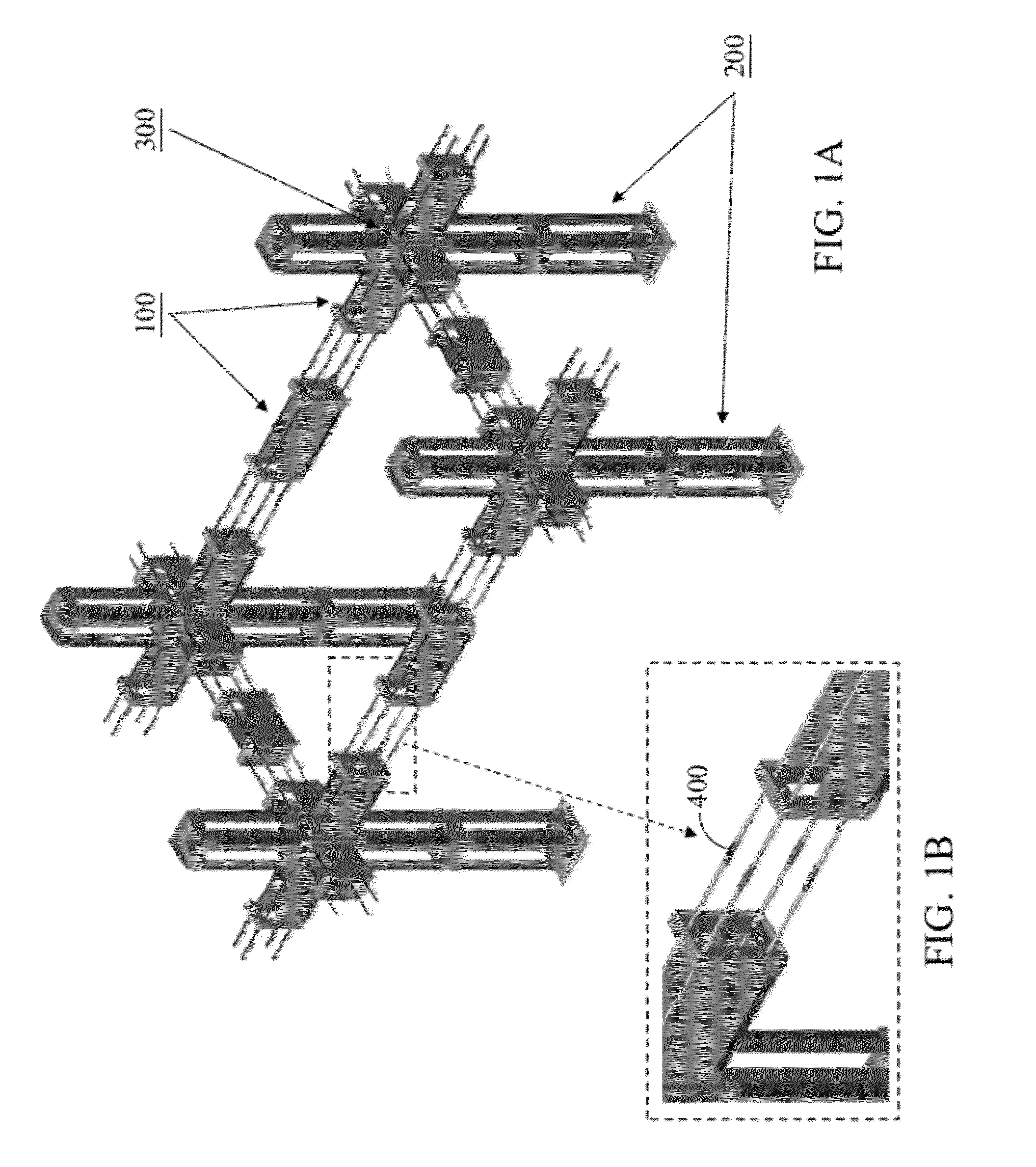
[0032]Referring to FIG. 1A, the present invention presents an architectured reinforcement structure, which is composed of a plurality of interconnected steel box units. According to the present invention, a steel box unit is designed to have various side plates and end plates, so that the steel box unit can be formed as a beam steel box unit 100, a column steel box unit 200, and a beam-column joint steel box unit 300. By interconnecting plural beam steel box unit 100, column steel box unit 200, and beam-column joint steel box unit 300 in the X direction, the Y direction, and the Z direction, an architectured reinforcement structure as shown in FIG. 1A can be provided.

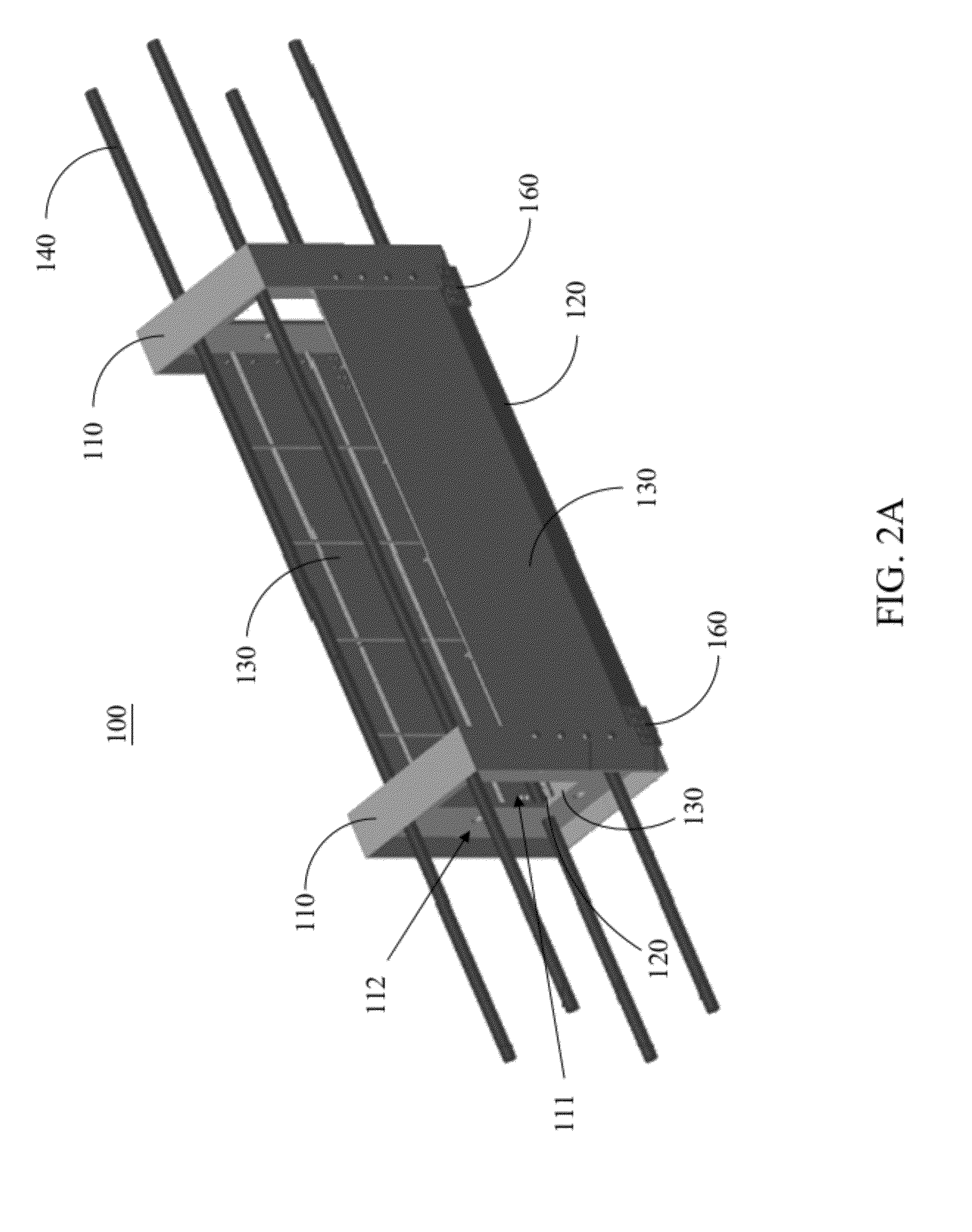
[0033]Refer to FIGS. 2A-2C. FIGS. 2A-2C illustrate an embodiment of a beam steel box unit of an architectured reinforcement structure of the present invention. A beam steel box unit 100 includes two end plates 110, two angle steel bars 120, three side plates 130, reinforcing steel bars 140, and steel rings 150, as shown...


PUM

PropertyMeasurementUnit
angleaaaaaaaaaa
circumferenceaaaaaaaaaa
cross-section area ratioaaaaaaaaaa

Abstract

This invention presents a modified reinforced concrete structure, which has a steel structure composed of a beam steel box unit, column steel box unit, and beam-column joint steel box unit with lap jointing reinforced steels. The side plate and / or end plate of the steel box has through holes for concrete flowing therebetween. In this way, the workability of concrete grouting and tamping are improved, and the phenomena of hive, segregation, or floating can be avoided. It can also enhance the performance of beam-column joints (e.g. with better confinement ability, etc.). Applying the invention, the efficiency and accuracy of constructing beam-column joints can be increased, and in addition to better ensure the structural safety, it can also reduce construction manpower and schedule.

Description

BACKGROUND OF INVENTION[0001]1. Field of Invention[0002]This invention relates to a modified reinforced concrete structure, which has less than 4% cross-section area ratio of steel, thus is referred as a modified reinforced concrete structure with respect to conventional SRC structure.[0003]2. Description of the Prior Art[0004]With the development of various construction materials and applications, the modern architecture has various diversities, in which the walls of the building structure, floor structure also have a lot varieties. Such varieties of wall and floor structures facilitate the building designers, and constructors to select the appropriate wall plate with an appropriate unit weight, compressive strength, lateral tensile strength in construction, and then consider the suitability of the construction costs, so that the design of buildings can be more convenient and flexible.[0005]In conventional reinforced concrete structures, only simple overlap is used between steel or...

Claims


Application Information

Patent Timeline
Patent Type & Authority Applications(United States)
IPC IPC(8): E04B1/19
CPCE04B1/30E04B1/165
Inventor PAN, CHAN-PINGHWANG, CHAO-LUNGCHANG, CHUNG-CHUANCHIANG, YU-HSIEN
Owner NAT TAIWAN UNIV OF SCI & TECH
Why Eureka
Try Eureka