Correction of Low Accuracy Clock

a low-accuracy, clock technology, applied in the field of electronic devices, can solve the problems of significant inaccuracy in the counted time value, wide tolerances of the typical low-power oscillator, and large drift with temperature and voltage, so as to correct the relationship of oscillations

Active Publication Date: 2012-12-06
TELEFON AB LM ERICSSON (PUBL)
View PDF3 Cites 13 Cited by
  • Summary
  • Abstract
  • Description
  • Claims
  • Application Information

AI Technical Summary

Benefits of technology

[0049]Using this method, two calibrations are obtained, which gives information about the change in the frequency of the second oscillator from the first calibration time period to the second calibration time period. This therefore represents a drift in the frequency of the second oscillator. Based on this information, it is possible to more correctly relate the oscillations of the second oscillator to real time passed. Thus, if an event is to take place, say, 1 second after the second calibration, the first and second calibration results are easily used to calculate how many oscillations the second oscillator must go through in order for it to correspond to 1 second in real time. Note that knowing the first and second calibration results allows us to make a prediction of the future frequency of the second oscillator following the second calibration. Thus continued drift in the second oscillator is therefore easily taken into account when determining the number of oscillations for the second oscillator to go through.

Problems solved by technology

However, this has the disadvantage that a typical low-power oscillator not only has wide tolerances, but also drifts significantly with temperature and voltage.
This has the effect that significant inaccuracies can build up in a counted time value that is derived from the low-power oscillator.

Method used


Image

  • Correction of Low Accuracy Clock
  • Correction of Low Accuracy Clock
  • Correction of Low Accuracy Clock

Examples


Embodiment Construction

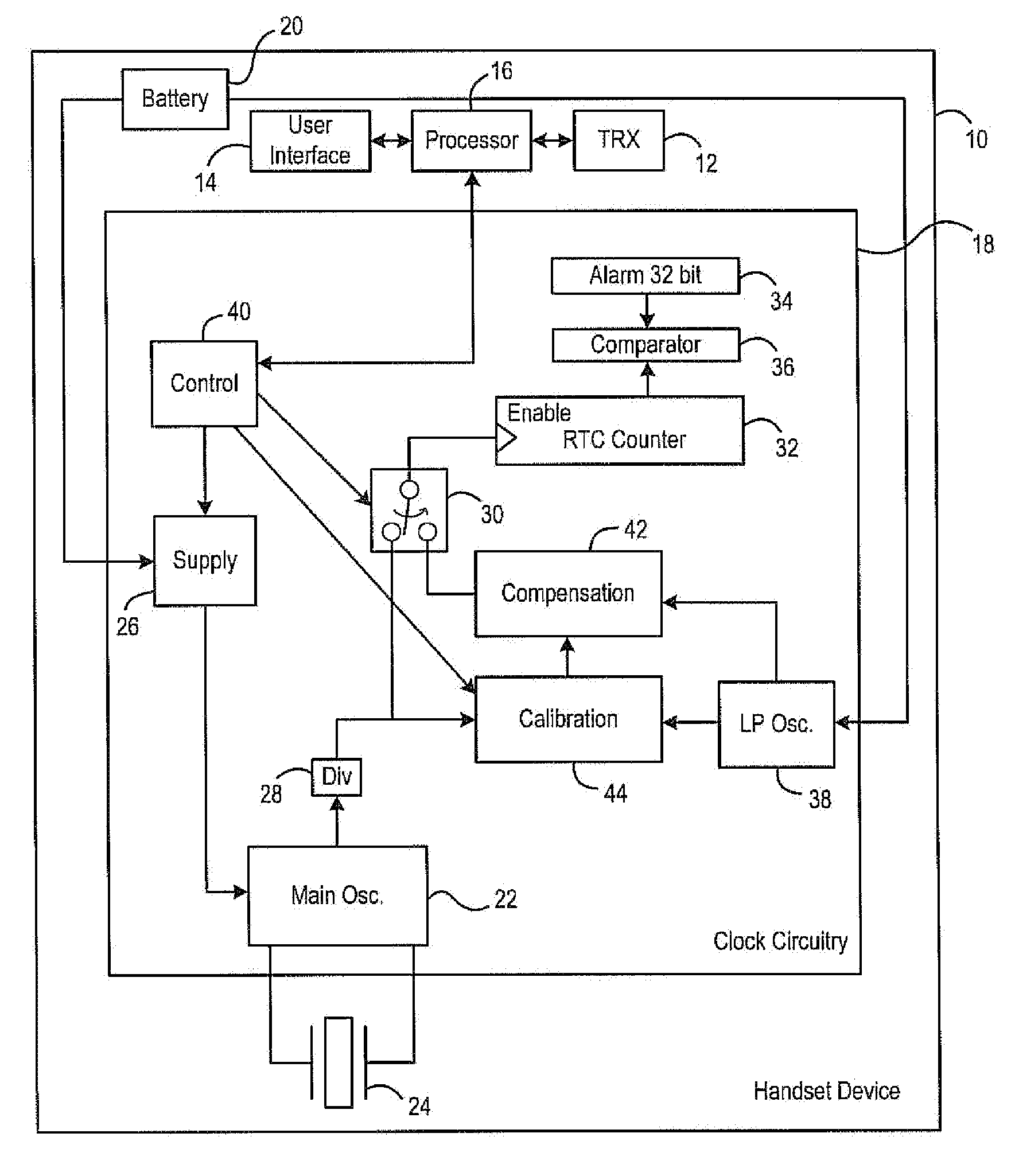
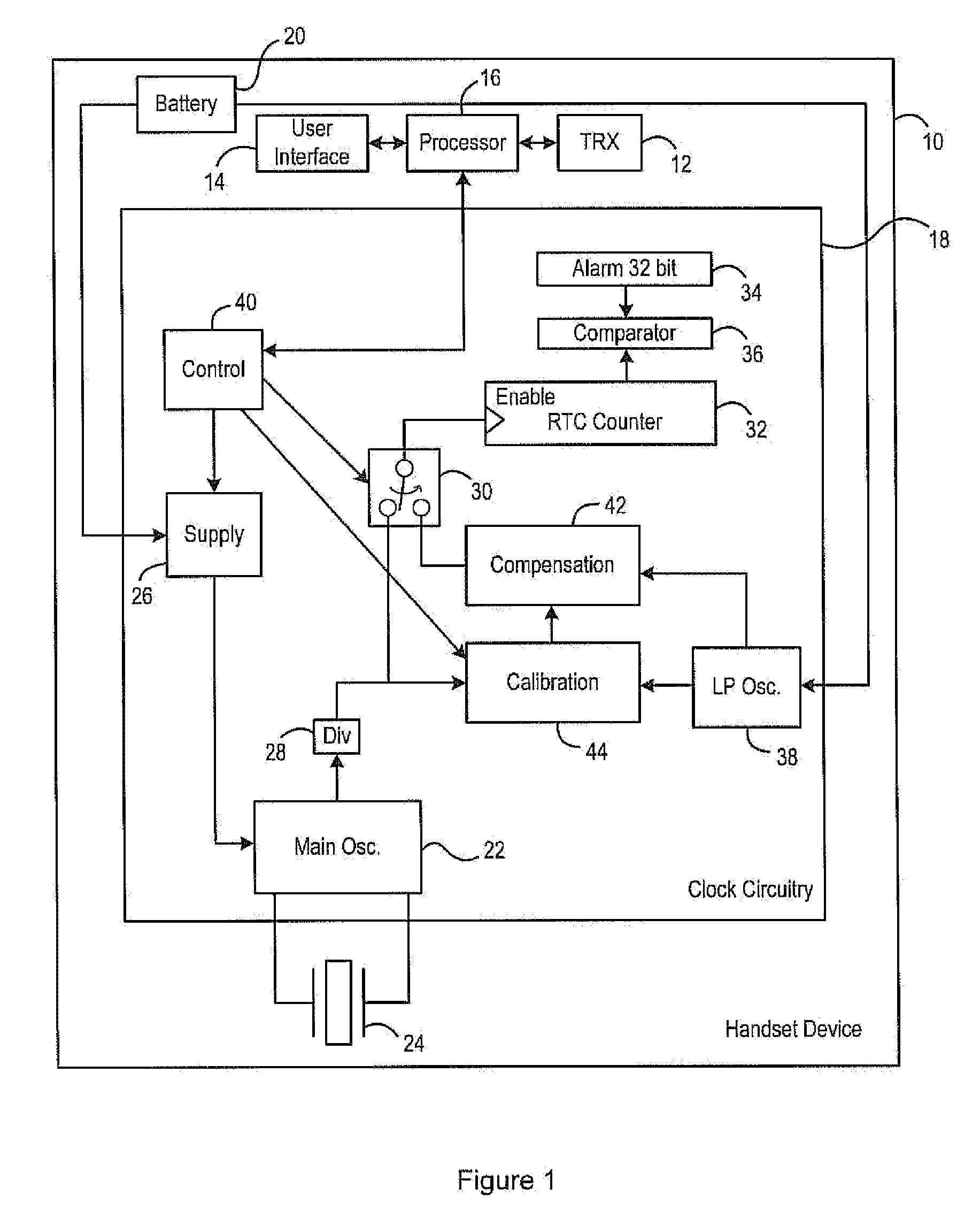
[0117]FIG. 1 shows an electronic device, in the form of a communications handset device 10, such as a mobile phone, although the invention is equally applicable to any electronic device, for example such as a portable computer or the like.

[0118]In this example, where the electronic device is a communications handset device, it includes wireless transceiver circuitry (TRX) 12 and a user interface 14, such as a touch screen or such as separate keypad and display devices, both operating under the control of a processor 16.

[0119]The device 10 further includes clock circuitry 18, which is illustrated schematically in FIG. 1, and the device including the clock circuitry 18 is powered by a battery 20.

[0120]The clock circuitry 18 includes a first oscillator in the form of a main oscillator circuit 22, which generates clock signals at a known frequency with an accuracy that is acceptable for all purposes of the device 10, using an oscillator crystal 24. Battery power is provided to the main ...


PUM


Abstract

An electronic device has two oscillators, for example a first highly accurate crystal oscillator and a second less accurate low power oscillator. In a normal mode of operation, time is counted based on an output from the crystal oscillator, but in a low power mode of operation, time is counted based on an output from the less accurate oscillator. During the low power mode of operation, a calibration process is performed repeatedly. During a first calibration time period the second oscillator is calibrated against the first oscillator to obtain a first calibration result, and a recalibration is performed during a second calibration time period to obtain a second calibration result. A correction factor is determined from the first and second calibration results, and the correction factor is applied when subsequently counting time based on the output from the second oscillator.

Description

[0001]This invention relates to an electronic device that uses an oscillator to count time. More specifically, the invention relates to a method of maintaining the count when the device is in a low power mode.[0002]It is known, for example from U.S. Pat. No. 6,650,189, to use a crystal-based oscillator to generate timing signals in a portable device. It is also known to power down the crystal-based oscillator in a standby mode whenever possible, in order to extend the battery life of the device. When the device is in the standby mode, an alternative low-power oscillator is used to generate the required timing intervals. In addition, the low-power oscillator is calibrated against the crystal-based oscillator at regular intervals. The result of the calibration is then used during a subsequent inter-calibration period when the low-power oscillator is being used to generate the required timing intervals.[0003]However, this has the disadvantage that a typical low-power oscillator not onl...

Claims


Application Information

Patent Timeline
Patent Type & Authority Applications(United States)
IPC IPC(8): H03L7/00
CPCG04G3/04G04G3/027
Inventor ELLIS, ANDREW
Owner TELEFON AB LM ERICSSON (PUBL)
Why Eureka
Try Eureka