Antenna system

a technology of antenna system and antenna array, which is applied in the direction of antenna array, basic electric elements, electric devices, etc., can solve the problem of limited operation range (i.e. distance between transmitter and receiver), and achieve the effect of increasing antenna size and/or power and efficiently being deployed

Active Publication Date: 2012-12-06
BAE SYSTEMS PLC
View PDF10 Cites 223 Cited by
  • Summary
  • Abstract
  • Description
  • Claims
  • Application Information

AI Technical Summary

Benefits of technology

[0005]The present inventors have realised it would be desirable to provide an antenna system or arrangement that gives a required range of operation by a solution other than that of increasing antenna size and/or power. The present inventors have realised this would be particularly d

Problems solved by technology

For a given phased array antenna, there will be limitations on its usef

Method used


Image

  • Antenna system
  • Antenna system
  • Antenna system

Examples


Embodiment Construction

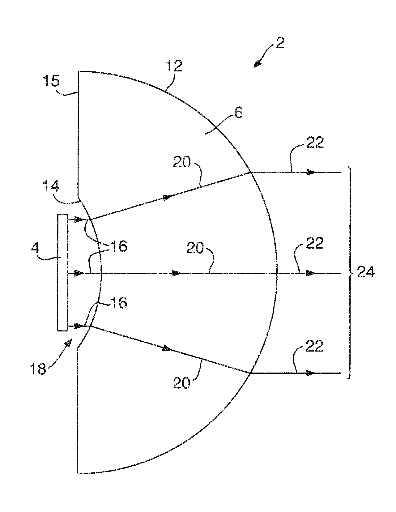
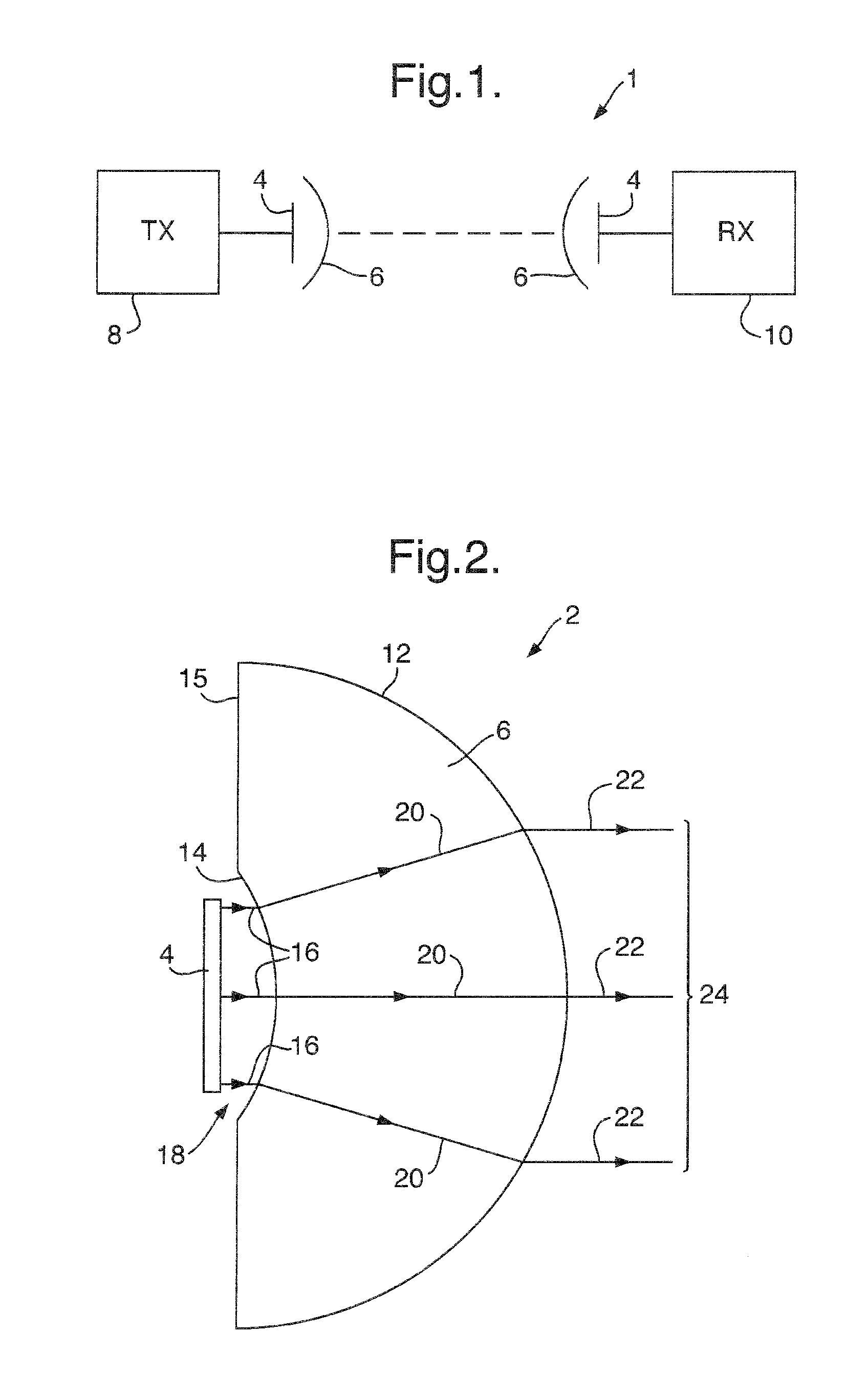
[0027]FIG. 1 is a schematic illustration (not to scale) of a first embodiment of a wireless system 1. The wireless system 1 comprises two antenna systems 2, which in this embodiment are the same as each other. Each antenna system 2 comprises a phased array antenna 4 and a dielectric lens 6. The phased array antenna 4 is placed in front of, and spaced apart, from the dielectric lens 6.

[0028]The phased array antenna 4 of a first of the antenna systems 2 (which may be termed the transmission antenna system) is electrically coupled to a transmission module 8. The phased array antenna 4 of the other of the antenna systems 2 (which may be termed the reception antenna system) is electrically coupled to a reception module 10.

[0029]The phased array antennas 4 are placed close to the respective dielectric lenses 6 so that in operation, in the case of transmission, millimetre waves emitted from the phased array antenna 4 pass through the dielectric lens 6 before continuing onwards away from th...


PUM


Abstract

An antenna system, comprising: a phased array antenna (4); and a dielectric lens arrangement (6), for example a single solid dielectric lens (6) comprising a substantially spherical convex surface (12) and a concave surface (14); wherein the dielectric lens arrangement (6) is arranged to magnify the effective aperture of the phased array antenna (4). The concave surface (14) is positioned within the near field of the phased array antenna (4). The phased array antenna (4) is operated at a frequency greater than or equal to 50 GHz. The antenna system retains some ability to electronically scan the beam. The antenna system may be for transmission and/or reception. The antenna system may be used for example for communication between two vehicles.

Description

FIELD OF THE INVENTION[0001]The present invention relates to wireless antenna systems and arrangements, in particular systems and arrangements including one or more phased array antennas.BACKGROUND[0002]Phased array antennas are well known, and are used for example to provide wireless links. One or more phased array antennas may provide transmission and one or more phased array antennas may provide reception.[0003]Signal processing arrangements for modulating and otherwise providing suitable transmission signals, and for receiving and demodulating received signals, are also well known.[0004]Phased array antennas and signal processing arrangements are provided in many variations for many different uses. In many applications, frequencies of less than 10 GHz are employed, requiring relatively large antenna sizes. For a given phased array antenna, there will be limitations on its useful range (i.e. distance between transmitter and receiver) of operation. Conventionally, to increase rang...

Claims


Application Information

Patent Timeline
IPC IPC(8): H01Q19/06H01Q21/00H01Q3/00
CPCH01Q3/30H01Q21/065H01Q19/062H01Q15/08
Inventor HENDERSON, ROBERT IANPESCOD, CHRISTOPHER RALPHNAWAZ, SHAHBAZ
Owner BAE SYSTEMS PLC
Why Eureka
Try Eureka