Image processing device, method and program

Inactive Publication Date: 2012-12-06
FUJIFILM CORP
5 Cites 3 Cited by

AI-Extracted Technical Summary

Problems solved by technology

Therefore, it is difficult to identify the position and direction of the ultrasonic image relative to the subject.
Therefore, it imposes significant time and labor on the user to display these moving images in a manner allowing comparison therebetween.
However, with the technique taught in Patent Document 1, a three-dimensional moving image taken with a CT apparatus and an ultrasonic moving image cannot be assoc...

Benefits of technology

[0022]According to the image processing device, method and program of the invention, a three-dimensional moving image showing a body part, which makes a predetermined periodic motion, of a patient and an ultrasonic moving image showing the body part are obtained; from a plurality of frame images forming the obtained three-dimensional moving image and ultrasonic moving image, a predetermined characteristic part having a shape that changes in response to the periodic motion is extracted; phases of the periodic motion captured in each of the three-dimensional moving image and the ultrasonic moving image are obtained, wherein, for at least one of the three-dimensional moving image and the ultrasonic moving image, the phases are obtained based on the shape of the extracted characteristic part; for each phase, a position of the characteristic part in a frame image forming the three-dimensional moving image corresponding to the phase is associated with a position of the characteristic part in a frame image forming the ultrasonic moving image corresponding to the phase based on the extracted characteristic part and the obtained phases; a superimposed ima...

Abstract

A three-dimensional moving image and an ultrasonic moving image showing a body part making periodic motion are obtained, and, from the moving images, a characteristic part having a shape that changes with the periodic motion is extracted. Phases of the periodic motion captured in the moving images are obtained. For at least one of the moving images, the phases are obtained based on the shape of the extracted characteristic part. For each phase, the positions of the characteristic part shown in the three-dimensional moving image and the ultrasonic moving image are associated with each other based on the extracted characteristic part and the obtained phases. A superimposed image is generated by aligning, for each phase, the positions of the characteristic part shown in the three-dimensional moving image and the ultrasonic moving image with each other based on the associated positions of the characteristic part and the phases, and displayed.

Application Domain

Technology Topic

Image

  • Image processing device, method and program
  • Image processing device, method and program
  • Image processing device, method and program

Examples

  • Experimental program(1)

Example

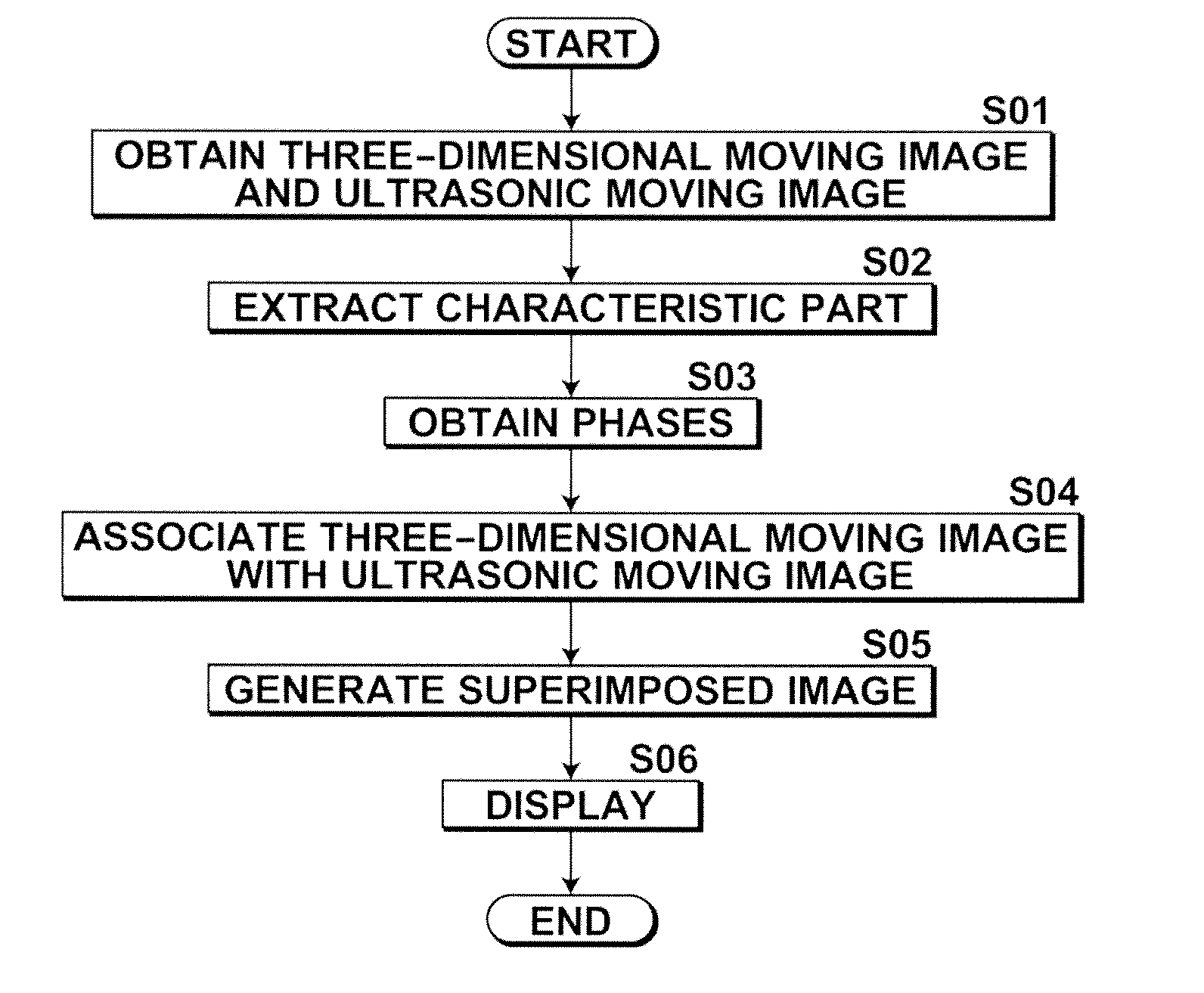
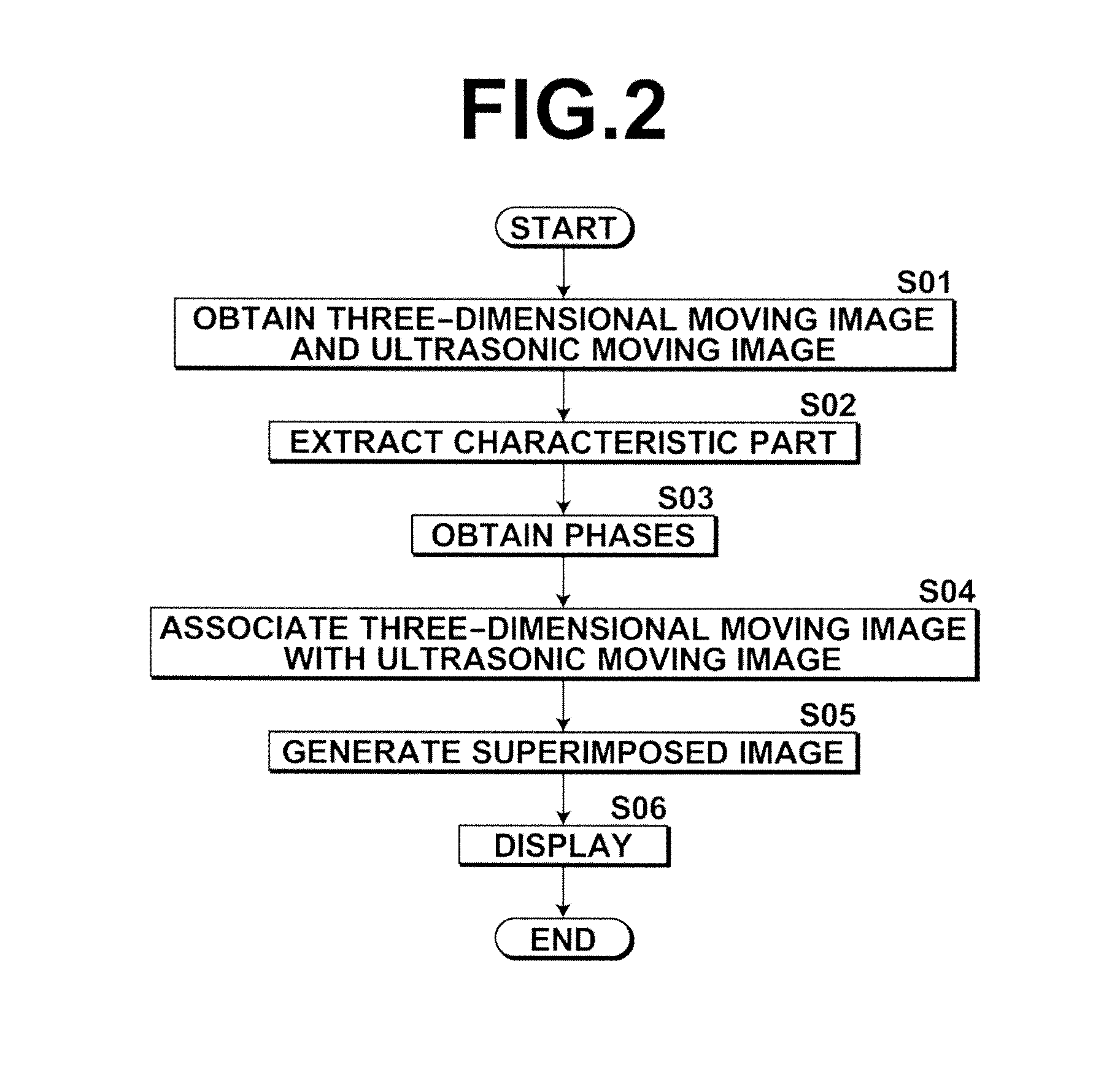
[0027]Hereinafter, embodiments of an image processing device, an image processing program and an image processing method of the present invention will be described in detail with reference to the drawings.
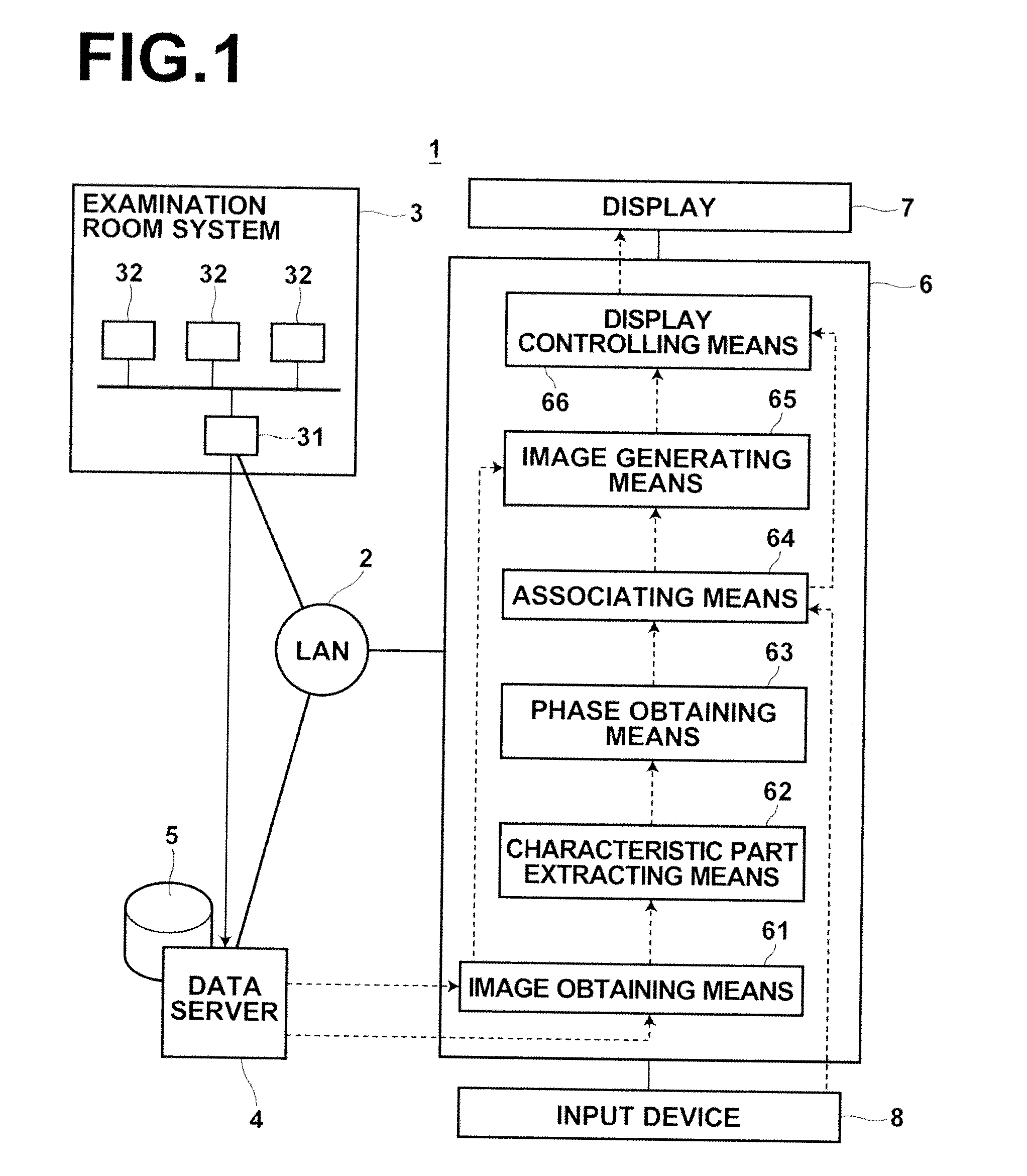
[0028]FIG. 1 illustrates the schematic configuration of a hospital system 1 incorporating an image processing device 6 according to one embodiment of the invention. The hospital system 1 includes an examination room system 3, a data server 4 and a diagnosis workstation (WS) 6, which are connected with each other via a local area network (LAN) 2.
[0029]The examination room system 3 includes various modalities 32 for imaging a subject, and an examination room workstation (WS) 31 used for checking and controlling images outputted from the individual modalities. The modalities 32 in this example includes a CT (Computed Tomography) apparatus and an MRI (Magnetic Resonance Imaging) apparatus, which are able to obtain a shape image representing shape information of the heart, and also includes an ultrasonic diagnostics apparatus, etc. Among these modalities 32, the CT apparatus and the MRI apparatus are compliant to the DICOM (Digital Imaging and Communication in Medicine) standard, and output the obtained volume data as a DICOM file with adding accompanying information.
[0030]The file outputted from each modality 32 is transferred to the data server 4 by the examination room WS 31. The data server 4 is formed by a computer with relatively high processing capacity including a high-performance processor and a mass memory, on which a software program for providing the function of a database management system (DBMS) is implemented. The program is stored in a storage, loaded in the memory upon startup, and executed by the processor. The data server 4 causes the file transferred from the examination room WS 31 to be stored in a mass storage 5. Further, in response to a request to search from the diagnosis WS 6, the data server 4 selects a file that meets a search condition from files stored in the mass storage 5 and sends the file to the diagnosis WS 6.
[0031]The diagnosis WS 6 is formed by a general-purpose workstation including a standard type processor, a memory and a storage, on which the image processing program for assisting diagnosis is implemented. The image processing program is installed on the diagnosis WS 6 from a recording medium, such as a DVD, or downloaded from a server computer connected via the network before being installed. A display 7 and an input device 8, such as a mouse and a keyboard, are connected to the diagnosis WS 6.
[0032]The image processing program implemented on the diagnosis WS 6 is formed by sets of program modules for accomplishing various functions. Among them is a set of program modules for accomplishing the image processing function. The program is stored in the storage, loaded in the memory upon startup, and executed by the processor. With this, the diagnosis WS 6 operates as: image obtaining means 61 for obtaining a three-dimensional moving image V1 showing a body part (the heart), which makes a predetermined periodic motion, of a patient and an ultrasonic moving image V2 showing the body part; characteristic part extracting means 62 for extracting, from a plurality of frame images forming the obtained three-dimensional moving image V1 and ultrasonic moving image V2, a predetermined characteristic part (mitral valve MV) having a shape that changes in response to the periodic motion; phase obtaining means 63 for obtaining phases of the periodic motion captured in the three-dimensional moving image V1 and the ultrasonic moving image V2, wherein, for at least one of the three-dimensional moving image V1 and the ultrasonic moving image V2, the phases are obtained based on the shape of the extracted characteristic part; associating means for associating, for each phase, the position of the characteristic part in a frame image forming the three-dimensional moving image corresponding to the phase with the position of the characteristic part in a frame image forming the ultrasonic moving image corresponding to the phase based on the extracted characteristic part and the obtained phases; image generating means 65 for generating a superimposed image of the three-dimensional moving image and the ultrasonic moving image by aligning, for each phase, a position of the characteristic part in a frame image forming the three-dimensional moving image V1 corresponding to the phase with a position of the characteristic part in a frame image forming the ultrasonic moving image V2 corresponding to the phase based on the associated positions of the characteristic part and the phases; and display controlling means 66 for displaying the generated superimposed image on the display device 7.
[0033]FIG. 2 is a flow chart illustrating the flow of image processing of this embodiment. FIG. 3 shows an example of the displayed superimposed image. Now, the flow of a process carried out by the functions of the WS 6 (image processing device) of this embodiment is described in detail using FIGS. 2 and 3. This embodiment is described in conjunction with the case of heart examination as an example.
[0034]Prior to the process of this embodiment, during the heart examination, a moving image of the chest of the subject including one period of heart beat is taken using a CT apparatus, or the like, and the thus taken three-dimensional moving image V1 (volume data) with the accompanying information added thereto is transferred as a DICOM file to the data server 4 and stored in the mass storage 5. The volume data is formed by a collection of pieces of voxel data representing a density distribution in a three-dimensional space. In each voxel data, X-ray absorption, or the like, is indicated as a voxel value. Further, a moving image of the chest of the same subject is taken by transesophageal echocardiography (TEE), which is ultrasound imaging carried out by inserting an ultrasound probe through the mouth to the esophagus, and the thus taken three-dimensional ultrasonic moving image V2 is transferred to the data server 4 and stored in the mass storage 5.
[0035]First, when an image processing function for the heart is selected on an initial screen and the patient ID number, the examination number, etc., are inputted on a predetermined input screen, the image obtaining means 61 sends the inputted information to the data server 4 and sends a request to search for and transfer the corresponding file stored in the mass storage 5.
[0036]The data server 4 which has received the above-described request searches for the requested file in the mass storage 5 and transfers the file to the image obtaining means 61. The image obtaining means 61 obtains the three-dimensional moving image V1 and the three-dimensional ultrasonic moving image V2 contained in the file transferred from the data server 4 and stores them in the memory (S01).
[0037]Subsequently, the characteristic part extracting means 62 extracts, as the predetermined characteristic part, the mitral valve MV, which is a heart valve located between the left ventricle LV and the left atrium LD, from each of the three-dimensional moving image V1 and the three-dimensional ultrasonic moving image V2 (S02).
[0038]In this example, the method taught in R. I. Ionasec et al., “Patient-Specific Modeling and Quantification of the Aortic and Mitral Valves From 4-D Cardiac CT and TEE”, IEEE TRANSACTIONS ON MEDICAL IMAGING, VOL. 29, NO. 9, pp. 1636-1651, 2010, is applied to the operations to extract the characteristic part and obtain the phases from the three-dimensional moving image V1 and the three-dimensional ultrasonic moving image V2.
[0039]The characteristic part extracting means 62 segments the mitral valve MV of the heart captured in the moving images V1 and V2 in time series for at least one period of heart beat according to the method taught in the above-mentioned Non-Patent Document, and extracts information for identifying the position of each sample point on the contour of the mitral valve MV in each frame image forming the moving images V1 and V2.
[0040]Then, the phase obtaining means 63 obtains the phase of heart beat of each frame image based on the position of each sample point on the contour of the mitral valve MV captured in the moving images V1 and V2 (S03).
[0041]The one period of heart beat include a systole and a diastole. At the end of the systole, the aortic valve AV changes from the open state to the closed state and the mitral valve MV starts to open from the closed state. At the end of the diastole, the mitral valve MV changes to the closed state and the aortic valve starts to open from the closed state. Using this nature, the phase obtaining means 63 identifies the end of diastole and the end of systole to identify the phases of heart beat.
[0042]In this embodiment, the shape of the mitral valve MV captured in each of the moving images V1 and V2 is obtained at predetermined time intervals using predetermined parameters according to the method taught in the above-mentioned Non-Patent Document, and the state of opening and closing of the mitral valve MV is identified based on the shape of the mitral valve MV to obtain the phase of heart beat corresponding to the state of opening and closing of the mitral valve MV. In this embodiment, for each of the moving images V1 and V2, the state of opening and closing of the mitral valve MV and the predetermined parameters representing the shape of the mitral valve MV are associated with each other and stored. The phase obtaining means 63 identifies, for each moving image V1, V2, a frame in which the mitral valve MV has changed from the open state to the closed state as a frame corresponding to the end of diastole of the heart beat. Also, the phase obtaining means 63 identifies, for each moving image V1, V2, a frame in which the mitral valve MV has changed from the closed state to the open state (start-to-open state) as a frame corresponding to the end of systole of the heart beat. The predetermined parameters representing the shape of the mitral valve MV may, for example, be distances between specific sample points on the contour of the mitral valve MV.
[0043]Then, the associating means 64 temporally associates the frames forming the moving images V1 and V2 with each other such that the moving images V1 and V2 are aligned with each other with respect to the phases corresponding to the end of systole and the end of diastole (the associating means 64 may perform interpolation in the time axis direction, as necessary) (S04). In this example, the frame images of the images V1 and V2 showing the same phase are associated with each other, and the spatial positions of the same characteristic part shown in the associated frame images are associated with each other.
[0044]In the above-described operation, in the case where the number of frames of the three-dimensional moving image V1 and the number of frames of the three-dimensional ultrasonic moving image V2 for one period differ from each other, the associating means 64 associates the frames of these images using the moving image having the smaller number of frames for one period as the reference. For example, the frames of the moving image having the greater number of frames for one period may be appropriately decimated, as necessary. Further, in the case where the phases of the associated frames are slightly out of alignment, interpolation may be performed using a known method so that each pair of corresponding frame images of the moving images shows the same phase. For example, the phase of each frame image forming one of the moving images may be obtained, and then, using frame images of the other of the moving images before and after the obtained phase, an interpolated frame image of the other of the moving images having the shape corresponding to the obtained phase may be generated by a known method, to associate the frame images of the one of the moving images with the thus generated frame images of the other of the moving images such that each pair of associated frame images shows the same phase.
[0045]The image generating means 65 generates volume rendered images for a series of frame images extracted from the three-dimensional moving image V1 by the above-described operation. For a series of frame images extracted from the three-dimensional ultrasonic moving image V2, the image generating means 65 generates images by transforming the coordinate system of the three-dimensional ultrasonic moving image V2 into the coordinate system of the three-dimensional moving image V1 so that the images V1 and V2 show the characteristic part associated by the associating means 64 in the same position, the same direction and the same size. Then, the image generating means 65 generates the superimposed image of the moving images V1 and V2 by a known method and stores the superimposed image in the storage 5 (S05).
[0046]Specifically, the image generating means 65 achieves the spatial alignment by transforming the coordinate system of one of the images into the coordinate system of the other of the images so that the images show the same characteristic part in the same spatial position based on the position associated by the associating means 64, and appropriately correcting the transformed coordinate system so that the images show the same characteristic part in the same spatial position, the same direction and the same size. It should be noted that, during the spatial position alignment, the associating means 64 obtains pixel spacing information of the three-dimensional moving image V1 and the three-dimensional ultrasonic moving image V2 from the DICOM header information of each image, and enlarges or reduces the moving images V1 and V2, as appropriate, based on the pixel spacing information to provide the series of frame images extracted from the three-dimensional moving image V1 and the three-dimensional ultrasonic moving image V2 with the same pixel spacing.
[0047]Further, as shown in FIG. 3, the superimposed image generated by the image generating means 65 of this embodiment shows voxel values based on the three-dimensional moving image V1 at a predetermined transparency by volume rendering, and as shown by arrow C in FIG. 3, shows voxel values and the direction of blood flow based on the three-dimensional ultrasonic moving image V2 by the known color Doppler method.
[0048]As the method for generating the superimposed images of the series of frame images extracted from the three-dimensional moving image V1 and the three-dimensional ultrasonic moving image V2, the image generating means 65 may apply any of various known generation method that allows display of the superimposed images of the series of frame images extracted from the moving images V1 and V2 such that the superimposed images show the same characteristic part in the same spatial position, the same direction and the same size.
[0049]The display controlling means 66 obtains the superimposed moving image (superimposed frame images) generated by the image generating means 65, and causes the display 7 to display the superimposed image, as shown in FIG. 3 (S06).
[0050]As described above, according to this embodiment, the phases of the periodic motion of the body part that makes a predetermined motion are obtained based on the shape of the characteristic part captured in the three-dimensional moving image V1 and the ultrasonic moving image V2 and the three-dimensional moving image V1 and the ultrasonic moving image V2 are aligned with each other with respect to the phases to achieve the spatial alignment based on the position of the characteristic part captured in the moving images. Therefore, even in a case where the electrocardiographic data of one of the moving images is not available, the moving images can appropriately be associated with each other. Further, by generating and displaying the superimposed image of the associated moving images, the user can understand the object of observation by compensating for low resolution areas of the ultrasonic moving image V2 with the high spatial resolution of the three-dimensional moving image V1, and can easily understand the information that is obtained only from the ultrasonic moving image at the same time. Therefore, the user can efficiently and accurately conduct the imaging diagnosis.
[0051]In this embodiment, the superimposed image of the ultrasonic moving image V2, which is shown by the color Doppler method based on the Doppler shift of blood flow, and the three-dimensional moving image V1 is displayed. Therefore, the user can preferably understand the body part of interest at high spatial resolution based on the three-dimensional moving image and the blood flow information, which is obtained only from the ultrasonic moving image, at the same time in an intuitive manner.
[0052]In this embodiment, the shape of the characteristic part is automatically recognized to be extracted from the three-dimensional moving image and the three-dimensional ultrasonic moving image to eliminate the need of manual operation by the user to extract the characteristic part, and thus the shape of the characteristic part can be extracted efficiently and easily.
[0053]In the case where the body part that makes a periodic motion is the heart and the predetermined characteristic part is any of the valves of the heart, the periodic motion of the heart is accurately identified based on the state of opening and closing of the valves of the heart, thereby preferably obtaining the phases. Further, in this case, the phase obtaining means obtains the phases by identifying the end of diastole and/or systole of the heart based on the state of opening and closing of the mitral valve and/or the aortic valve among the valves of the heart. Therefore, more accurate identification of the periodic motion of the heart is achieved based on the change of the shape of the characteristic part in response to the heart beat. Still further, in this embodiment, the associating means 64 aligns the moving images V1 and V2 with respect to the phases of heart beat (the end of systole and the end of diastole), thereby more accurately associating the moving images V1 and V2 with each other.
[0054]In this embodiment, the phases of both the three-dimensional moving image V1 and the ultrasonic moving image V2 are obtained by automatic recognition, and therefore the phases are easily and accurately obtained and associated. Alternatively, for one of the three-dimensional moving image and the three-dimensional ultrasonic moving image, the phases of the periodic motion may be identified based on the shape of the characteristic part, and for the other of the moving images, the phase of the periodic motion may be obtained based on the DICOM header information, or the like. In this case, the automatic recognition may be applied to only one of the moving images to minimize increase of computational load and efficiently obtain the phases of the moving images.
[0055]In this embodiment, the image generating means 65 generates the superimposed image by obtaining the pixel spacing from the accompanying information of each of the three-dimensional moving image V1 and the ultrasonic moving image V2, and providing the moving images with the same pixel spacing based on the obtained pixel spacing. This facilitates obtaining the pixel spacing of each moving image and accurately providing the moving images of the same size to generate the superimposed image.
[0056]In this embodiment, the above-described image processing is carried out based on the three-dimensional moving image V1 taken with a CT or MR apparatus and the three-dimensional ultrasonic moving image V2, and this provides the user with more detailed understanding of the object of observation.
[0057]The characteristic part extracting operation according to this embodiment may be achieved by applying the method taught in Y. Zheng et al., “Four-Chamber Heart Modeling and Automatic Segmentation for 3D Cardiac CT Volumes Using Marginal Space Learning and Steerable Features”, IEEE TRANSACTIONS ON MEDICAL IMAGING, Vol. 27, pp. 1668-1681, 2008. It should be noted that the characteristic part extracting means 62 may apply any of known various methods that can extract a characteristic part of a structure from the two three-dimensional moving images V1 and V2. For example, the user may manually input the position and shape of the characteristic part, such as the valves of the heart, using a mouse, or the like, for each of the three-dimensional moving images V1 and V2, and the image processing device may obtain such inputs to extract the position and the shape of the characteristic part.
[0058]The phase obtaining means 63 may determine the phases of heart beat by using any method that uses the nature that the aortic valve AV changes from the open state to the closed state and the mitral valve MV starts to open from the closed state at the end of systole, and the mitral valve MV changes to the closed state and the aortic valve starts to open from the closed state at the end of diastole. For example, a period from a point when the mitral valve MV starts to open from the closed state (the end of systole) to a point when the mitral valve MV again starts to open from the closed state (the end of systole) may be detected as the one period of heart beat to associate the images V1 and V2 such that the images are aligned with respect to the phase of the end of systole, or a period from a point when the mitral valve MV changes from the open state to the closed state (the end of diastole) to a point when the mitral valve MV again changes from the open state to the closed state (the end of diastole) may be detected as the one period of heart beat to associate the images V1 and V2 such that the images are aligned with respect to the phase of the end of diastole. Alternatively, for example, the phases of heart beat may be determined based on the state of opening and closing of the aortic valve AV, in place of the mitral valve MV, or information of the state of opening and closing of the mitral valve MV and information of the state of opening and closing of the aortic valve AV may be weighted to be used to determine the phase of heart beat.
[0059]In the case where any of various characteristic parts, such as the left ventricle LV, the left atrium LA, the right ventricle RV, the right atrium RA, the valves MV, AV, PV and TV and the apex AC of the heart, as shown in FIG. 3, or any combination of these characteristic parts is used as the predetermined characteristic part to identify the periodic motion of the heart based on the periodical change of the shape depending on the phase of heart beat, similarly to this embodiment, the phases are accurately obtained. In the case where more than one characteristic parts are used to identify the periodical motion of the heart, the phases are more accurately obtained based on the more than one pieces of information.
[0060]If the moving image V1 and/or the moving image V2 contains two or more periods of periodic motion, the phase obtaining means 63 may arbitrarily specify a period used to associate the moving images V1 and V2 with each other. The phase obtaining means 63 according to this embodiment receives an input by the user via a mouse and/or keyboard to identify one of the periods specified by the user by using any known method. For example, period selection buttons corresponding to the two or more periods contained in the three-dimensional moving image V1 or the three-dimensional ultrasonic moving image V2 may be displayed to receive the selection of period by the user, or the user may be prompted to input the start time of one of the periods contained in the three-dimensional moving image V1 or the three-dimensional ultrasonic moving image V2 via a keyboard, or the like, and the phase obtaining means 63 may receive the selection of period by the user.
[0061]FIG. 4 shows an example of the displayed superimposed image according to a modification of the above-described embodiment. Although the above-described embodiment is described in conjunction with the three-dimensional ultrasonic moving image V2 as an example, it is apparent for those skilled in the art that the invention is similarly applicable to a two-dimensional moving image as long as the image shows a cross section showing a recognizable characteristic part included in a body part, such as a cross section P showing the ventricles LV and RV, the atriums LA and RA, the valves MV, AV, PV and TV and the apex AC of the heart, as shown in FIG. 4. The user can observe, with respect to a predetermined cross section including the characteristic part, a high spatial resolution image taken with a CT or MR apparatus, and can understand information, such as information of blood flow, which is obtained only from a two-dimensional moving image taken with an ultrasonic diagnostics apparatus at the same time. This facilitates the user to accurately conduct the imaging diagnosis.
[0062]It should be noted that the present invention is not limited to this embodiment. For example, the predetermined body part may be any body part that makes a predetermined periodical motion, such as flexion and extension of a knee joint. In the case where the invention is applied to flexion and extension of the knee, or the like, one or more parts forming the knee joint may be segmented to obtain parameters representing the state of flexion and extension of the knee, such as distances between predetermined points on the thigh bone and the shinbone, from the segmented parts, and the phases of the periodical motion from the flexed state to the extended state may be obtained based on the parameters representing the state of flexion and extension.
[0063]It should be noted that the alignment of the three-dimensional moving image V1 taken with a CT or MR apparatus and the ultrasonic moving image V2 may be achieved by transforming the coordinate system of the three-dimensional moving image V1 taken with a CT or MR apparatus into the coordinate system of the ultrasonic moving image V2.
[0064]The associating means 64 may associate the phases of the three-dimensional moving image V1 taken with a CT or MR apparatus and the ultrasonic moving image V2 for only a part of one period of periodic motion, for one period of periodic motion, or for two or more periods of periodic motion.
[0065]Although the embodiments of the present invention have been described with respect to the case where the image processing program of the invention is implemented on a single diagnosis WS to cause the WS to function as the image processing device, the image processing program may be installed on two or more computers in a distributed manner to cause the two or more computers to function as the image processing device.

PUM

no PUM

Description & Claims & Application Information

We can also present the details of the Description, Claims and Application information to help users get a comprehensive understanding of the technical details of the patent, such as background art, summary of invention, brief description of drawings, description of embodiments, and other original content. On the other hand, users can also determine the specific scope of protection of the technology through the list of claims; as well as understand the changes in the life cycle of the technology with the presentation of the patent timeline. Login to view more.

Similar technology patents

Classification and recommendation of technical efficacy words

Why Eureka
Try Eureka