Apparatus for phase-contrast imaging comprising a displaceable x-ray detector element and method

a detector element and phase-contrast technology, applied in the field of xray image acquisition, can solve the problems of limiting the usable size of the x-ray detector element, affecting the identification of individual elements of the interior of the object to be examined, and affecting the quality of the image acquisition, so as to achieve the effect of reducing the readability

Inactive Publication Date: 2012-12-06
KONINKLIJKE PHILIPS ELECTRONICS NV
View PDF0 Cites 28 Cited by
  • Summary
  • Abstract
  • Description
  • Claims
  • Application Information

AI Technical Summary

Benefits of technology

[0023]Even in phase-contrast imaging a single projection may comprise superimposed structures and thus may also benefit from a tomosynthesis mode of operation. Accordingly, employing a phase-contrast system capable of tomosynthesis may overcome the diminished readability by superposition of anatomical structures.
[0024]The requirement of sufficient fringe visibility of, e.g. sufficiently large intensity modulations in phase-contrast imaging, in particular differential phase-contrast imaging, may impose restriction on the degrees of freedom of relative motion betw...

Problems solved by technology

However, a certain object may have only a minor attenuation of X-radiation or differences in attenuation even within different tissues in the inside of the object, thus resulting in a rather uniformly attenuated X-ray image having low contrast and so impeding distinguishing individual elements of the ...

Method used


Image

  • Apparatus for phase-contrast imaging comprising a displaceable x-ray detector element and method
  • Apparatus for phase-contrast imaging comprising a displaceable x-ray detector element and method
  • Apparatus for phase-contrast imaging comprising a displaceable x-ray detector element and method

Examples


Embodiment Construction

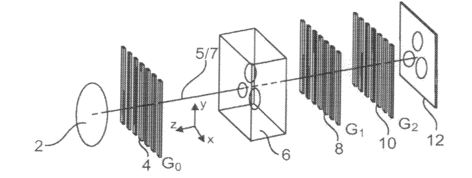
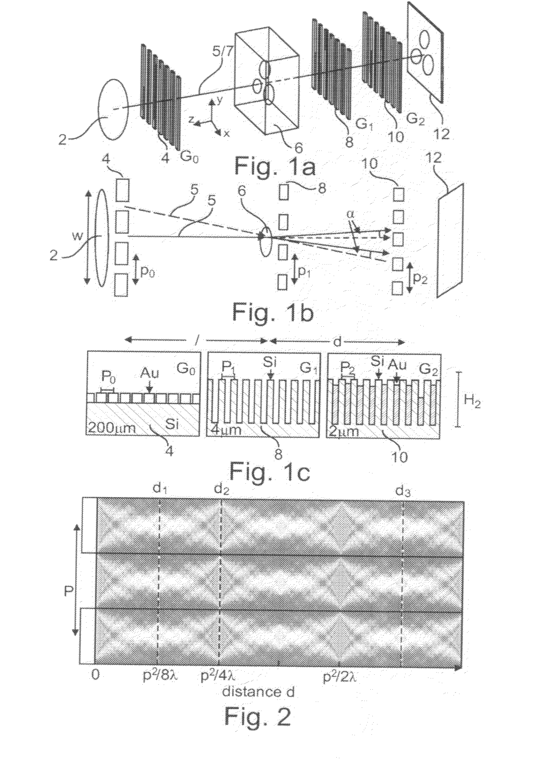
[0082]Now referring to FIGS. 1a-c, an exemplary embodiment of an apparatus for phase-contrast imaging according to the present invention is depicted.

[0083]FIG. 1a shows a three-dimensional representation of an exemplary embodiment of an apparatus for phase-contrast imaging. A rather large X-ray source 2 is arranged adjacent to a source grating 4. Since X-ray source 2 may be considered to be incoherent due to its size with respect to the wavelength of the radiation emitted, the source grating G0 4 is employed for providing a plurality of single coherent X-ray sources as depicted by the two arrows in FIG. 1b.

[0084]X-radiation 5 is emanating from X-ray source 2 in the direction of the optical axis 7 possibly constituting a fan-beam or cone-beam of X-rays. The respective shape of the X-ray beam is not depicted in FIG. 1a.

[0085]X-radiation 5 is arriving at object 6, penetrating object 6, subsequently arriving at a beam splitter grating G1 8. The trenches or gaps of the beam splitter gr...


PUM


Abstract

The present invention relates to X-ray image acquisition technology in general. Employing phase-contrast imaging for X-ray image acquisition may significantly enhance the quality and information content of images acquired. However, phase-contrast information may only be obtainable in a small detector region, possibly being too small for a sufficient field of rotation view for specialized X-ray imaging applications. Accordingly, an apparatus for phase-contrast imaging is provided that may allow the acquisition of an enlarged field of view. According to the present invention an apparatus (1) for phase-contrast imaging is provided, comprising an X-ray source (2), an X-ray detector (12) element having a detector size, a beam splitter grating (8) and an analyzer grating (10). An object (6) is arrangeable between the X-ray source (2) and the X-ray detector (12). The beam splitter grating (8) and the analyzer grating (10) are arrangeable between the X-ray source (2) and the X-ray detector (12). X-ray source (2), the beam splitter grating (8), the analyzer grating (10) and the X-ray detector (12) are operatively coupled such that a phase-contrast image of the object (6) is obtainable. The apparatus (1) is adapted for acquiring a phase-contrast image having a field of view larger than the detector size. The X-ray detector element (12) is displaceable and by the displacement of the X-ray detector (12) a phase-contrast image of the field of view is obtainable.

Description

FIELD OF THE INVENTION[0001]The present invention relates to X-ray image acquisition in general. More particularly, the present invention relates to image acquisition employing phase-contrast. In particular, the present invention relates to an apparatus for phase-contrast imaging comprising a displaceable X-ray detector element, an X-ray system, a method for acquiring phase-contrast image information and the use of an apparatus for phase-contrast imaging in one of an X-ray system, a CT system and a tomosynthesis system.BACKGROUND OF THE INVENTION[0002]In X-ray image acquisition technology, an object to be examined, e.g. a patient, is situated between an X-ray generating device or X-ray source, e.g. an X-ray tube, and an X-ray detector. A fan-beam or cone-beam is generated by the X-ray source, possibly employing collimation elements, in the direction of the X-ray detector. The object to be examined situated in the path of the X-radiation is spatially attenuating the X-ray beam, depen...

Claims


Application Information

Patent Timeline
IPC IPC(8): G01N23/04
CPCA61B6/00A61B6/032A61B6/4291A61B6/484A61B6/4092A61B6/4021
Inventor ROESSL, EWALDENGEL, KLAUS JUERGENVOGTMEIER, GEREONGELLER, DIETERMARTENS, GERHARDSCHUSSER, SABASTIAN SIEGMUNDKOEHLER, THOMAS
Owner KONINKLIJKE PHILIPS ELECTRONICS NV
Why Eureka
Try Eureka