
Active Tracking for Free-Space Optical Communication Systems

Inactive Publication Date: 2012-12-06
SKYFIBER
View PDF6 Cites 56 Cited by
  • Summary
  • Abstract
  • Description
  • Claims
  • Application Information

AI Technical Summary

Benefits of technology

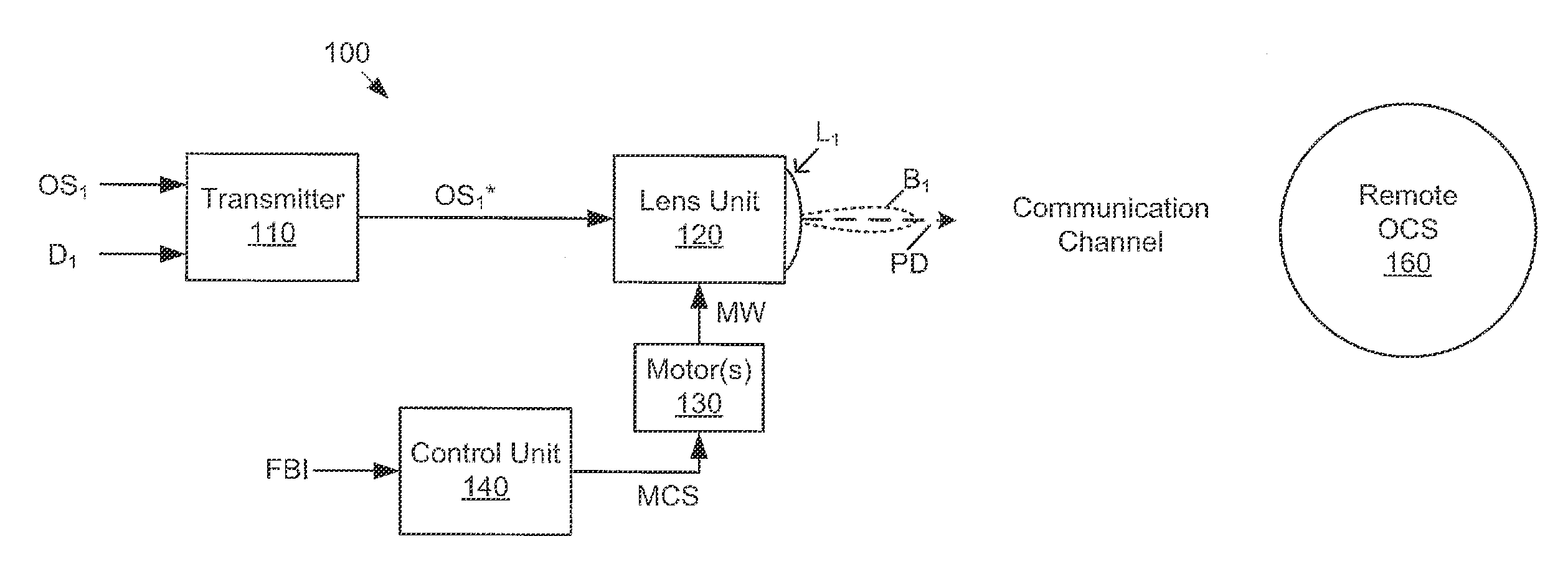
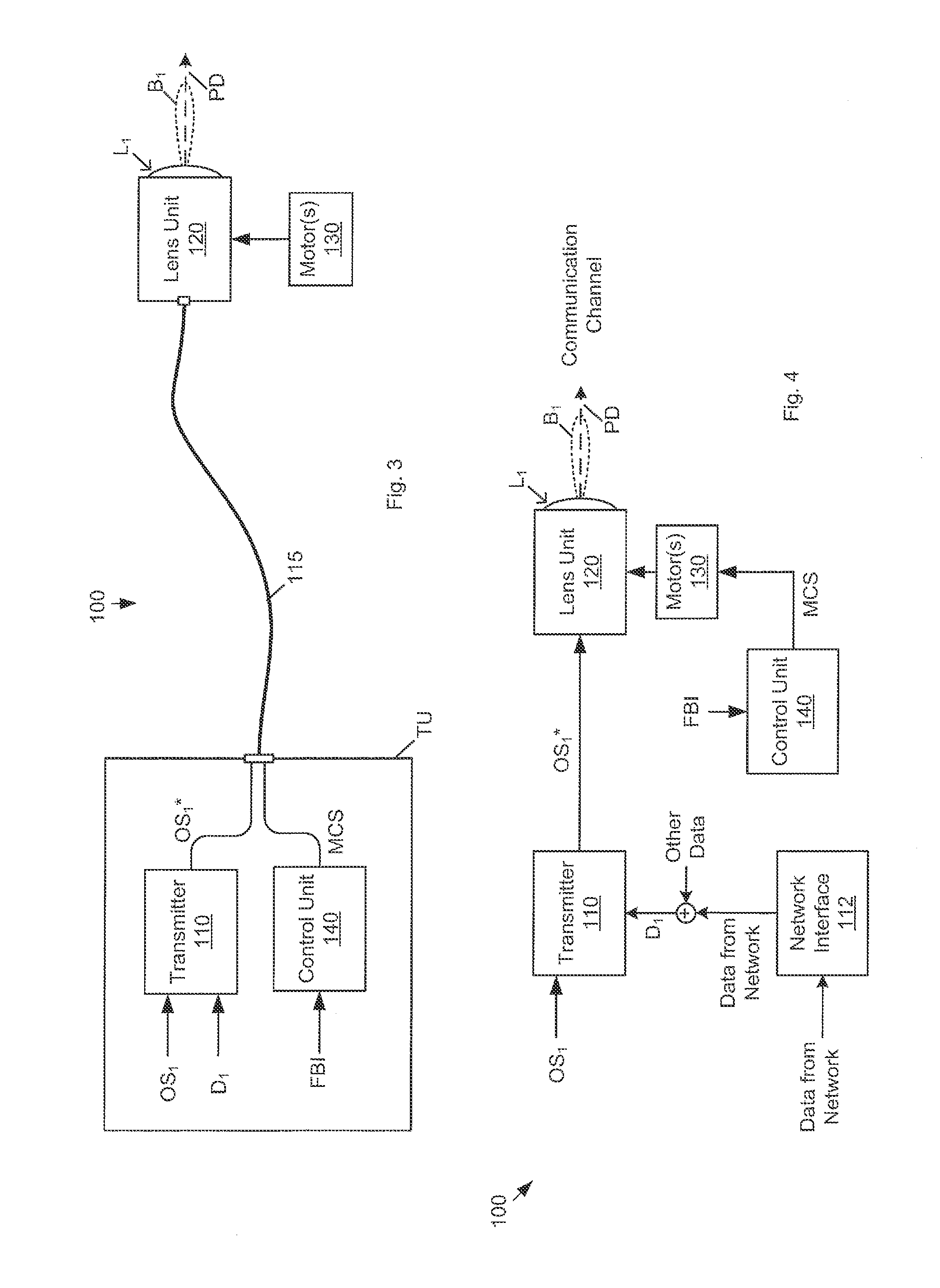
[0018]In some embodiments, each node includes two optical antennas, i.e., a receive antenna and a transmit antenna. The tracking algorithm may compensate for collimation errors between the two antennas.
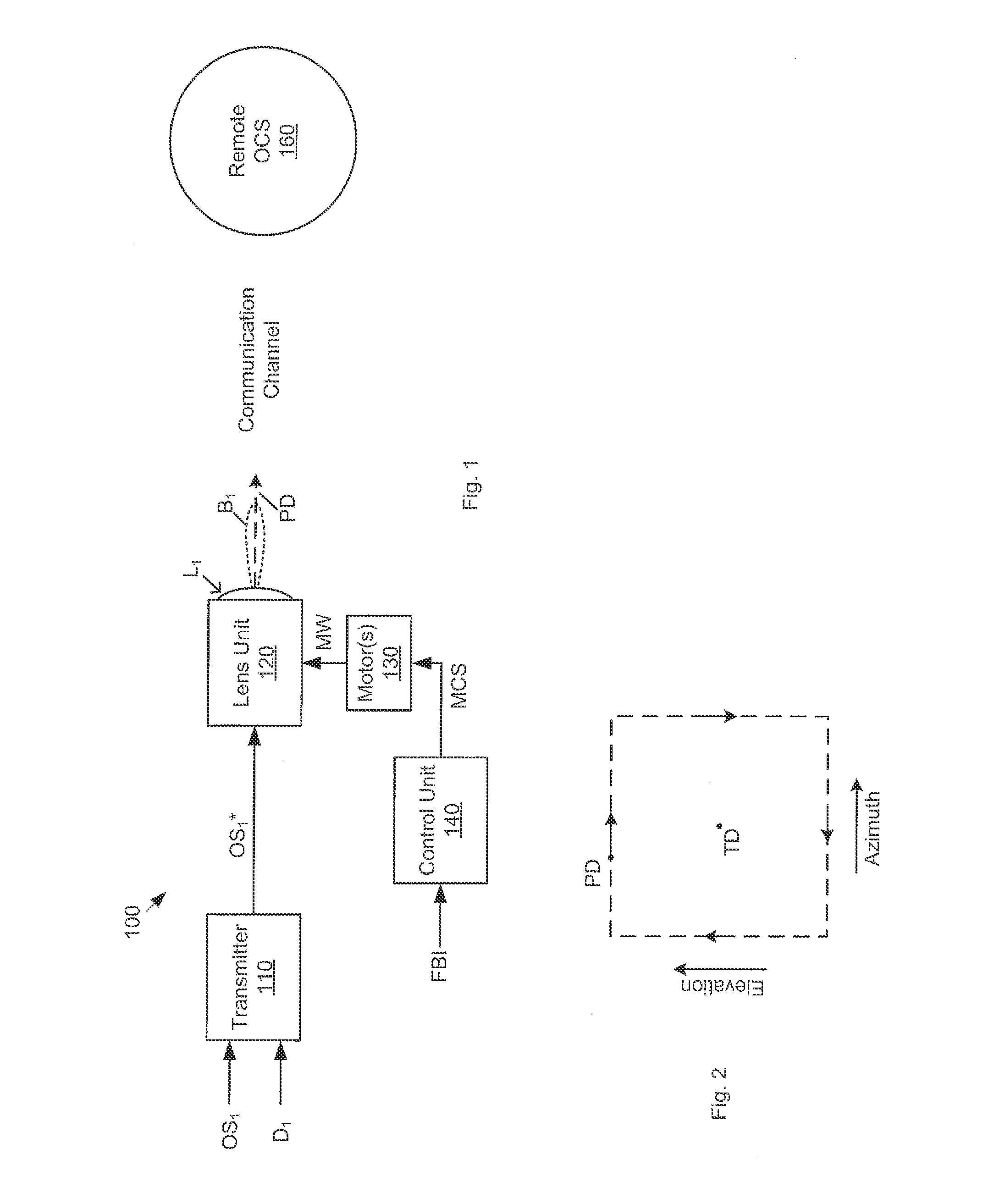
[0051]In some embodiments, the scan is rectangular, where only one motor is active at a time, to minimize power consumption.

Problems solved by technology

However, millimeter-wave systems are impacted by rainfall but not fog.
All of the RF systems are subject to FCC licensing rules and regulations, which may involve additional cost at licensed frequencies.
Unlicensed RF systems are subject to interference, which leads to reduced data rates as multiple users may operate on those frequency bands simultaneously.
However, the pricing does not reflect that demand due to high competition.
Until recently, the cost of Gigabit systems has been relatively high.
In the field of optical free-space communications, one major challenge in establishing reliable communications is keeping narrow laser beams on target in the presence of structural movement.
The degree of instability rises as you go from building to towers and from towers to monopoles.
As the degree of instability increases, it becomes increasingly more difficult to keep the beams on target.
One difficulty in maintaining alignment is because the laser beams used in at least some optical free-space communication systems are relatively narrow and much smaller than the amount of movement seen on structures.
Current optical communication systems for deployment on unstable structures are limited in their capability.
These crude solutions cause the cost of the optical communication system to increase.
High-speed tracking may be required when optical antennas are mounted on unstable structures.
When the optical wireless system is placed / mounted on an unstable structure, the optical tracking system may need to be agile.
Thus, another source of angular error is available to the near end should there be failure in communications.

Method used


Image

  • Active Tracking for Free-Space Optical Communication Systems
  • Active Tracking for Free-Space Optical Communication Systems
  • Active Tracking for Free-Space Optical Communication Systems

Examples


Embodiment Construction

[0111]Incorporations by Reference

[0112]The following patents are hereby incorporated by reference in their entireties.

[0113]U.S. Pat. No. 5,786,923, issued on Jul. 28, 1998, entitled “Point-To-Multipoint Wide Area Telecommunications Network Via Atmospheric Laser Transmission through a Remote Optical Router”.

[0114]U.S. Pat. No. 6,348,986, issued on Feb. 19, 2002, entitled “Wireless Fiber-Coupled Telecommunication Systems Based on Atmospheric Transmission of Laser Signals”.

[0115]U.S. Pat. No. 6,931,183, issued on Aug. 16, 2005, entitled “Hybrid Electro-Optic Cable for Free Space Laser Antennas”.

Terminology

[0116]The following is a glossary of terms used in the present document.

[0117]Memory Medium—A memory medium is a medium configured for the storage and retrieval of information. Examples of memory media include: various kinds of semiconductor memory such as RAM and ROM; various kinds of magnetic media such as magnetic disk, tape, strip, film, etc.; various kinds of optical media such ...


PUM


Abstract

Systems and methods enabling nodes of a free-space optical communication system to maintain pointing alignment of their transmitted optical beams. A first node scans its optical antenna through a path centered on a target direction. The second node captures signal strength measurements during the scan, and sends those measurements to the first node. The first node separately measures signal strength of the optical signal being received from the second node. The two sources of information (locally measured and remotely measured) are used to compute angular errors. The first node uses the angular errors to adjust the target direction of its optical antenna. The second node may employ the same method (with roles reversed) to adjust its target direction. By cycling back and forth between to the two nodes, the target directions of the two nodes maintain alignment in spite of movements of the structures on which they are mounted.

Description

RELATED APPLICATION DATA[0001]This application claims the benefit of priority to U.S. Provisional Application No. 61 / 493,354, filed on Jun. 3, 2011, entitled “Active Tracking for Free-Space Optical Communication Systems”, invented by Sheth, Walters, Wissel, Xu, Royal and Hawkins, which is hereby incorporated by reference in its entirety.FIELD OF THE INVENTION[0002]The present invention relates to the field of free-space optical communication, and more particularly, to a mechanism enabling optical communication systems to keep their optical antennas pointed at each other in spite of movements in the structures on which the optical antennas are mounted.DESCRIPTION OF THE RELATED ART[0003]In the field of wireless communications, there are presently two types of systems prevalent in industry: radio frequency systems and optical frequency systems. The radio frequency systems operate at frequencies below 100 GHz. The optical systems operate at wavelengths from 860 nm to 10.6 μm. The main ...

Claims


Application Information

Patent Timeline
IPC IPC(8): H04B10/10
CPCH04B10/118H04B10/1125
Inventor SHETH, SAMIR S.WALTERS, WAYNE E.WISSEL, JOHN C.XU, KELVIN HUIROYAL, BRIAN E.HAWKINS, KELLY P.
Owner SKYFIBER
Learn More