[0018]It is an object of the present disclosure to provide a purge apparatus which can carry out a purge process wherein the reaching concentration of a predetermined gas
atmosphere is high and by which a replacing operation with a purge nozzle having a tip end portion, that is, a port contacting portion, different in type or shape or an operation for maintenance of a purge nozzle can be carried out simply and smoothly in accordance with a type or a shape of a port attached to a purge object vessel.
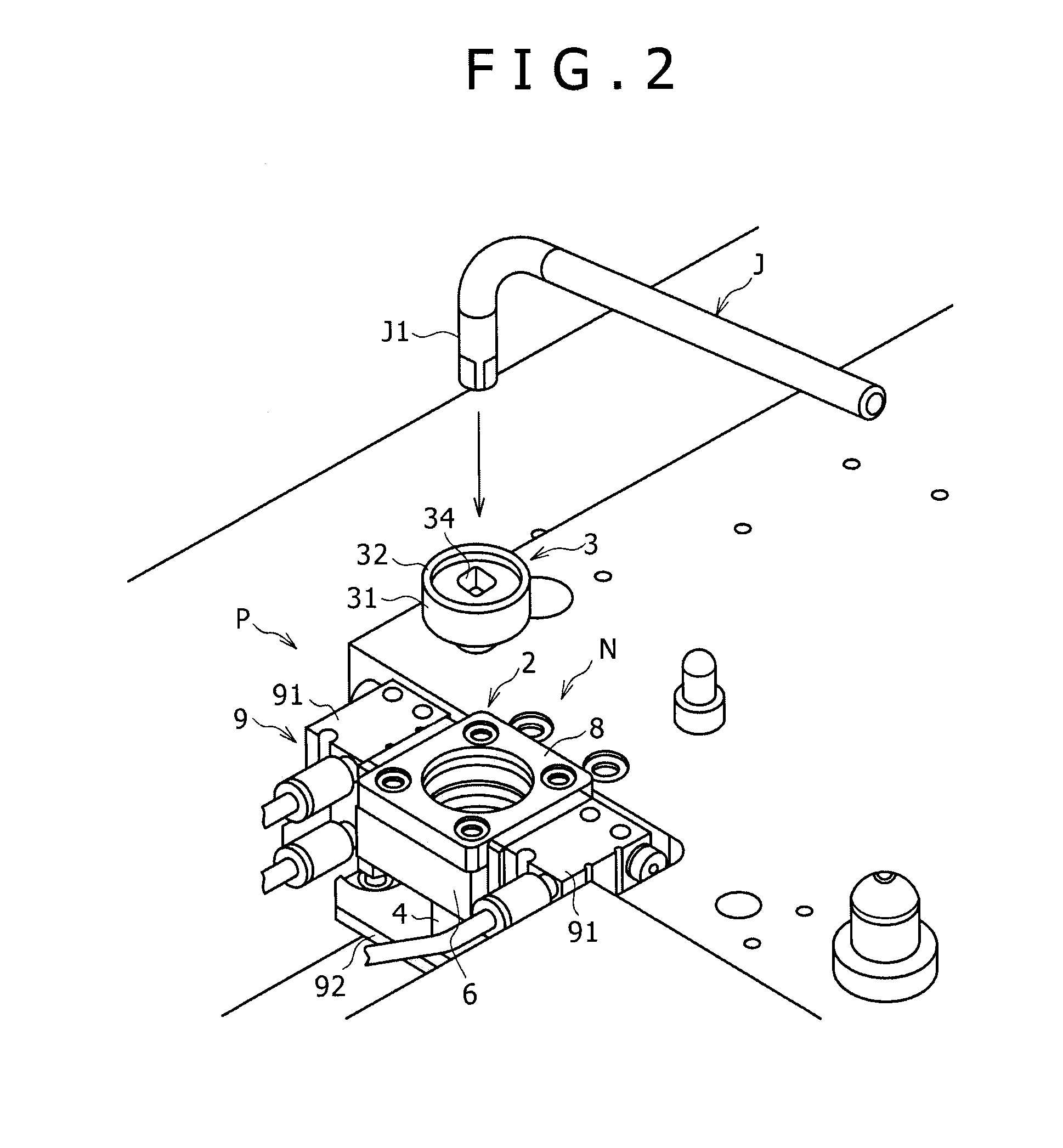
[0021]Since, in the purge apparatus according to the present disclosure, the bottom purge nozzle main body is removably attached to the bottom purge unit provided on the receiving table in this manner, where the nozzle is to be changed to a nozzle of a different type in response to the type or the shape of the port which is different depending upon the type or the like of the purge object vessel, only the bottom purge nozzle main body can be changed over suitably without requiring complicated operation of removing and re-mounting the entire unit from and on the receiving table. Further, it is possible to secure a good contacting state in which high
air tightness between the bottom purge nozzle main body and the port is secured. Further, where the port contacting portion of the bottom purge nozzle main body capable of contacting with the port is abraded, damaged or deformed depending upon time-dependent deterioration or the
frequency of use or where the compatibility between the purge object vessel and the port is not good, a good contacting state in which high air tightness with the port is secured can be secured by replacing the bottom purge nozzle main body with a new bottom purge nozzle main body or a different bottom purge nozzle main body which is not abraded, damaged or deformed.
[0022]Further, since the port contacting portion of the bottom purge nozzle main body in the purge apparatus according to the present disclosure is positioned at a
fixed position in a state in which the attachment object portion of the bottom purge nozzle main body engages with the attachment portion of the bottom purge unit, in comparison with an alternative mode in which a seal member for exclusive use is interposed between the port and the bottom purge nozzle main body to secure high air tightness, the seal member for exclusive use is not required. Further, a horizontal datum plane of the purge object vessel prescribed in the standards can be set with high accuracy without taking the heightwise size of the seal member into consideration. In addition, since the port contacting portion of the bottom purge nozzle main body in the purge apparatus according to the present disclosure is placed substantially horizontally in a state in which the attachment object portion of the bottom purge nozzle main body engages with the attachment portion of the bottom purge unit, in comparison with an alternative mode in which the bottom purge nozzle main body is simply thrust into and attached to the bottom purge unit, a wavering behavior of the bottom purge nozzle main body with respect to the bottom purge unit can be prevented and suppressed. Further, the port of the purge object vessel can be contacted with the port contacting portion placed substantially horizontally in a state in which high air tightness is secured.
[0023]Further, in the purge apparatus according to the present disclosure, as a mode in which the attachment object portion of the bottom purge nozzle main body and the attachment portion of the bottom purge unit are engaged with each other, not only a mode in which one of the attachment object portion and the attachment portion is a recessed portion and the other one of the portions is a projected portion such that the recessed portion and the projected portion are engaged with each other but also another mode in which the attachment object portion is inserted into the attachment portion and pivotally turned in a predetermined direction so that the purge apparatus is placed into a locked state can be adopted. However, a mode in which the attachment object portion is a male screw or a female screw and the attachment portion is a male screw or a female screw corresponding to the attachment object portion such that the male screw is screwed into the female screw is preferable in that the structure is simple and replacing operation of the bottom purge nozzle main body can be carried out easily and smoothly.
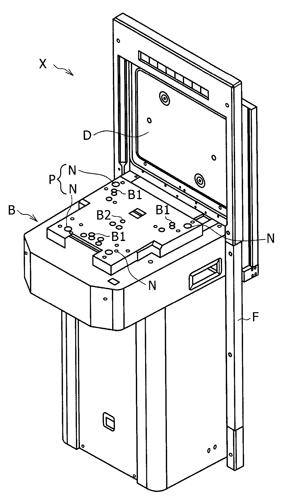
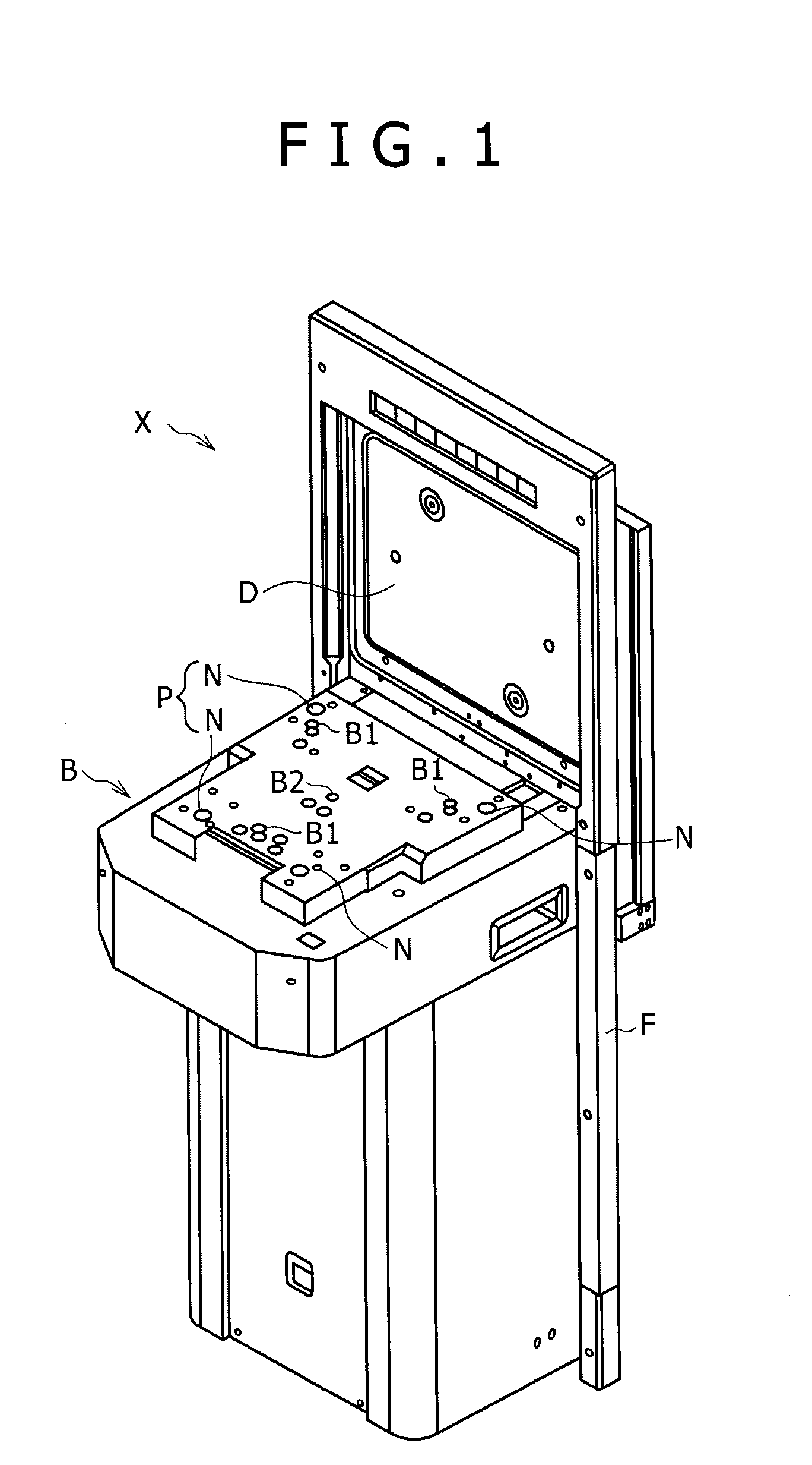
[0025]With such a load port as described above, the working effects described can be implemented by the purge apparatus, and, by replacing the bottom purge nozzle main body with another bottom purge nozzle main body suitable for an applied one of FOUPs which are different in type or shape of the port, high air tightness can be secured in a state in which the purge nozzle and the port are contacted with each other. Consequently, a purge process by which a high reaching concentration of a predetermined gas
atmosphere can be achieved can be carried out efficiently and accurately.
[0026]According the present disclosure, a purge process by which a high reaching concentration of a predetermined gas atmosphere can be achieved can be carried out for the purge target container by adopting the novel technical idea that the bottom purge nozzle main body is removably mounted on the bottom purge unit. Further, replacing operation of replacing the bottom purge nozzle main body with another bottom purge nozzle main body which is different in type or shape of a tip end portion, which is the port contacting portion, in accordance with the type or the shape of the port attached to the purge target container, and maintenance operation of the bottom purge nozzle main body can be carried out easily and smoothly. Further, with the purge apparatus and the load port, high air tightness can be secured in a contacting state of the purge apparatus with the port of the purge object container.

