Power generation apparatus

a power generation apparatus and power technology, applied in lighting and heating apparatus, steam engine plants, water feed control, etc., can solve the problems of increasing the risk of cavitation occurring in the circulating pump, damage to the pump, and affecting the operation of the pump, so as to reduce the risk of cavitation in the pump and achieve a high amount of liquid-state working medium.

Inactive Publication Date: 2012-12-13
KOBE STEEL LTD
View PDF6 Cites 16 Cited by
  • Summary
  • Abstract
  • Description
  • Claims
  • Application Information

AI Technical Summary

Benefits of technology

[0021]According to this configuration, it is objectively determined whether or not the channel upstream from the pump is filled with liquid-state working medium based on the value detected by the liquid surface meter (level gauge), which makes it easy to ensure that a state where the channel upstream from the pump is filled with liquid-state working medium and thus makes it possible to further reduce the risk of cavitation in the pump; furthermore, because the liquid tank is provided, a high amount of liquid-state working medium can be ensured in the channel upstream from the pump.
[0022]As described thus far, according to the present invention, the occurrence of cavitation in a pump that circulates a working medium can be suppressed without complicating the structure.

Problems solved by technology

For example, if the fluid mechanism is a turbo fluid mechanism, the impeller, which is the primary component thereof, will be damaged.
Because no measures are taken in the stated waste heat electric power generator to preempt the occurrence of cavitation in the circulating pump, there is the risk that cavitation will occur in the circulating pump.
However, the aforementioned Japanese Patent No. 4557793 makes no particular mention of a method for stopping the waste heat electric power generator or, conversely, a method for starting the waste heat electric power generator.
This further increases the risk of cavitation occurring in the circulating pump.

Method used


Image

  • Power generation apparatus
  • Power generation apparatus
  • Power generation apparatus

Examples


first embodiment

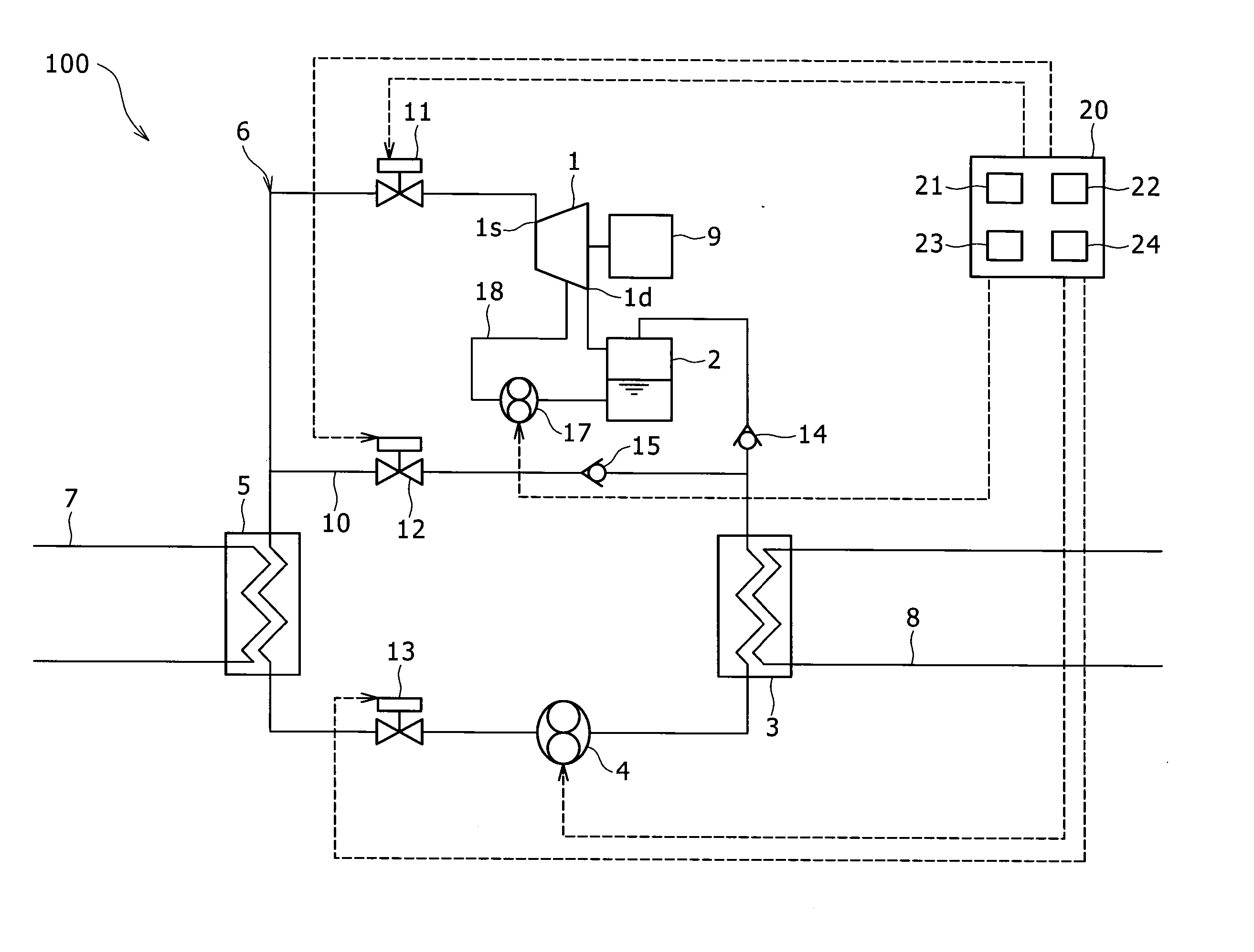
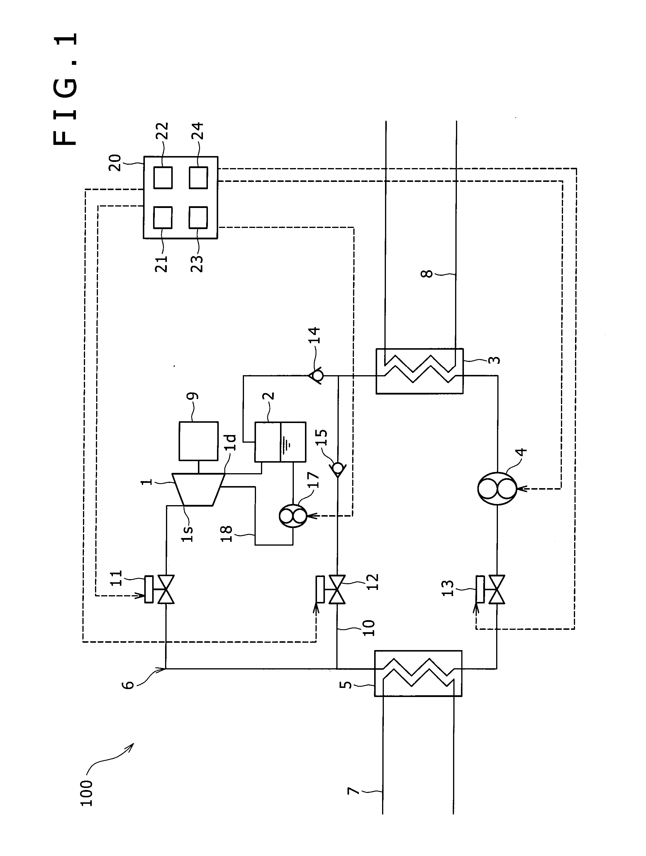
[0030]FIG. 1 illustrates the configuration of an electric power generator 100 according to a first embodiment of a power generation apparatus according to the present invention.

[0031]The electric power generator 100 includes a closed-loop circulating channel 6 in which are provided an expander 1, an oil separator 2, a condenser (condensing means) 3, a working medium pump 4, and an evaporator (steam generator, steam generation means) 5. A Freon-based medium (for example, R245fa) is injected into the circulating channel 6 as a working medium. A medium with a lower boiling point than that of water is used, and the electric power generator 100 according to the present embodiment is configured as a binary electric power generator.

[0032]The expander 1 is disposed downstream from the evaporator 5 in the circulating channel 6, and obtains kinetic energy from the working medium by expanding the working medium evaporated by the evaporator 5 (vapor). The expander 1 is configured of, for exampl...

second embodiment

[0052]FIG. 4 illustrates the configuration of an electric power generator 100 according to a second embodiment of a power generation apparatus according to the present invention. Note that the second embodiment will describe only points that differ from the first embodiment, and descriptions of configurations, actions, and effects that are the same as in the first embodiment will be omitted.

[0053]In the electric power generator 100 according to the second embodiment, in addition to the constituent elements of the electric power generator 100 according to the first embodiment, the condenser 3 is provided with a liquid surface meter (level gauge) 16 capable of detecting the height of the liquid surface therein. Furthermore, the setting unit 21 in the control unit 20 outputs a setting signal to the RAM so that a predetermined value of the liquid surface meter (level gauge) 16 is set to a value inputted through the input / display means. The determination unit 24 of the control unit deter...

third embodiment

[0060]FIG. 6 illustrates the configuration of an electric power generator 100 according to a third embodiment of a power generation apparatus according to the present invention. Note that the third embodiment will describe only points that differ from the second embodiment, and descriptions of configurations, actions, and effects that are the same as in the first embodiment and the second embodiment will be omitted.

[0061]In the electric power generator 100 according to the third embodiment, in addition to the constituent elements of the electric power generator 100 according to the second embodiment, a liquid tank 16a is provided in the circulating channel 6 between the condenser 3 and the pump 4, and the liquid surface meter (level gauge) 16 is provided in the liquid tank 16a rather than in the condenser 3.

[0062]The control operations performed when starting and stopping the pump 4 of the electric power generator 100 according to the present embodiment are the same as in the second...


PUM


Abstract

A power generation apparatus that suppress cavitation includes a first on/off valve provided between a steam generator and an expander in a circulating channel; a bypass channel connected between an area between the steam generator and the first on/off valve and an area between the expander and a condenser; a second on/off valve provided in the bypass channel; a third on/off valve provided between a pump and the steam generator; and a controller. When stopping the pump, the controller outputs a control signal that stops the pump, a control signal that closes the first on/off valve, a control signal that opens the second on/off valve, and a control signal that closes the third on/off valve. In the case where a predetermined condition has been met, the controller outputs a control signal that closes the second on/off valve.

Description

BACKGROUND OF THE INVENTION[0001]1. Field of the Invention[0002]The present invention relates to power generation apparatuses used in electric power generators and the like.[0003]2. Description of the Related Art[0004]Recent years have, due to concerns for energy conservation, seen an increased need for electric power generators that collect so-called “waste heat” from various types of facilities such as factories and generate electricity using the energy from the collected waste heat.[0005]The waste heat electric power generator disclosed in, for example, Japanese Patent No. 4557793 is known as such an electric power generator. This waste heat electric power generator includes a closed-loop circulating channel in which a working fluid evaporator, a turbine for causing the working fluid vapor to expand, a condenser for condensing the working fluid vapor, and pumps for circulating the working fluid are connected in series. Thermal cycling is carried out in the circulating channel whe...

Claims


Application Information

Patent Timeline
Patent Type & Authority Applications(United States)
IPC IPC(8): F01K13/02F01K9/02
CPCF01K13/02F01K23/10F01K25/02F01D15/10F01K3/22
Inventor TSUBOI, NOBORUMATSUMURA, MASAYOSHI
Owner KOBE STEEL LTD
Why Eureka
Try Eureka