
System and method to deliver and control power to an arc furnace

a technology of arc furnace and system, applied in the field of power supply, can solve the problems of a large number of problems in the power system, insufficient process control, and more severe or catastrophic outcomes,

Inactive Publication Date: 2012-12-13
WARNER POWER
View PDF42 Cites 11 Cited by
  • Summary
  • Abstract
  • Description
  • Claims
  • Application Information

AI Technical Summary

Benefits of technology

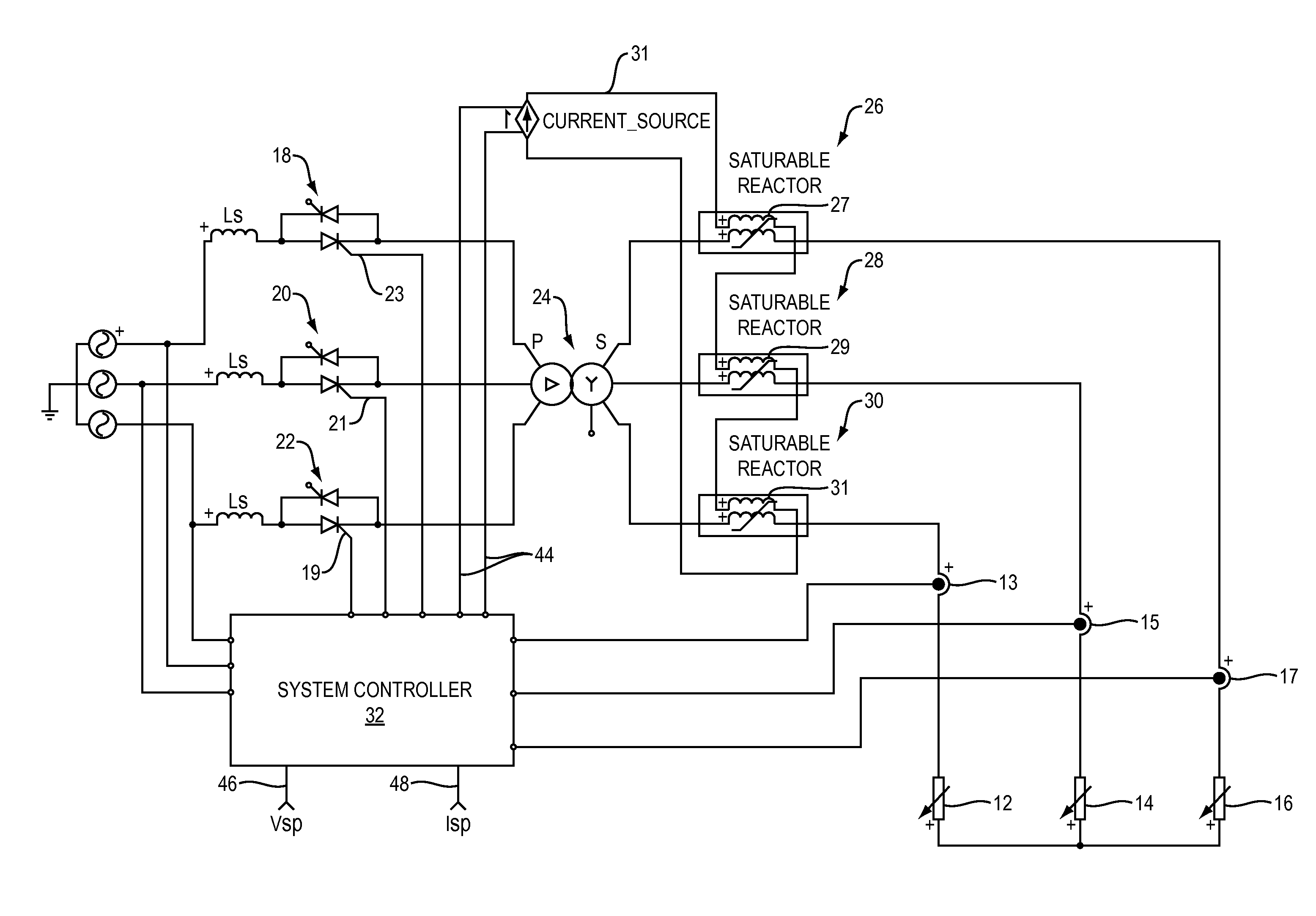
[0007]The proposed approach is based on the idea of inserting a saturable-reactor in the output path between the transformer and the electrodes. This reactor is controlled through an external DC power source to control the permeability of the core of the reactor and therefore the series impedance. The saturable-reactor acts as a current limiting device that prevents damage to the electrodes and the input elements of the power supply and allows the decoupling of the control knobs for the arc such as current and voltage.

Problems solved by technology

However, regardless of the type of arc furnace, the main challenge in designing a power supply capable of delivering the adequate energy to maintain the arc or re-ignite at each cycle reside in the dynamic, non-linear and chaotic nature of the load.
Arcs are known to cause a multitude of problems to the power system as well as many performance limitations such as flicker effect, unbalance and harmonic currents.
More severe or catastrophic outcomes are also common and are generally caused by instabilities in the control system and the inherent transients.
A thorough review of the techniques employed thus far shows that process control is not fully attained and most control algorithms fail to maintain a stable operation throughout the range of variation of the load.
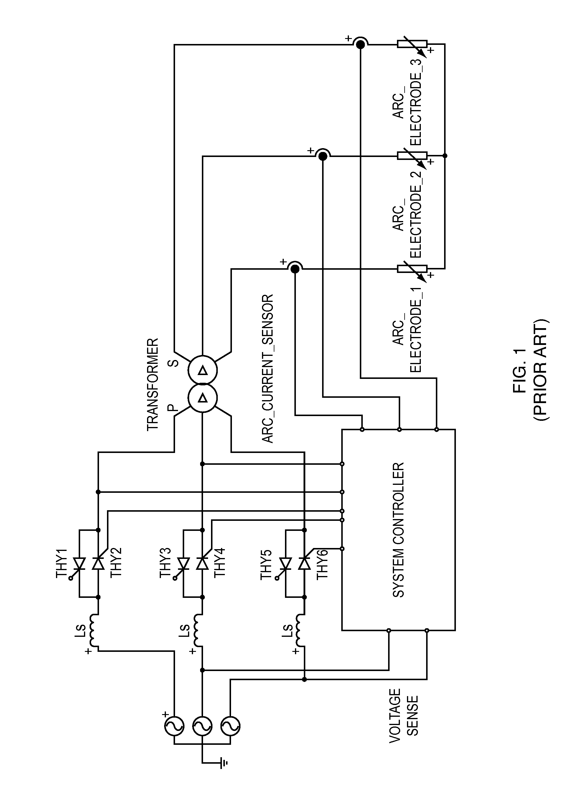
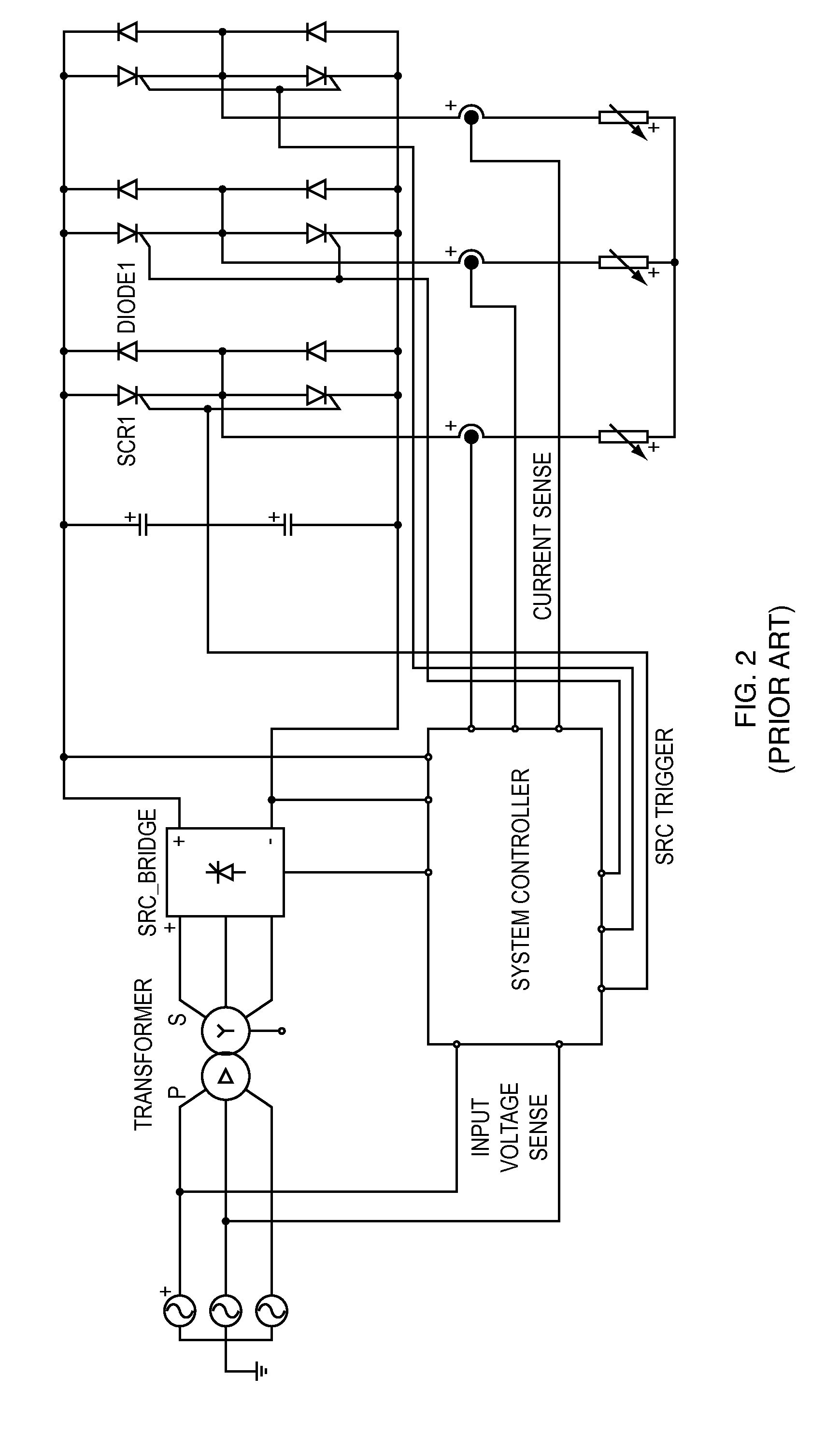
These systems and control methods suffer major drawbacks such as the non-ability to control current and voltage independently, which therefore limits the operating range and does not allow for a smooth arc ignition and turn-off thereby reducing the life of the electrodes.
In addition to complex control, major filtering is required to manage flicker effects and harmonics.
Such a topology allows the quasi decoupling of output current and voltage yet it adds complexity and cost.
Such elements add a pole to the transfer function of the system which increase the possibility of oscillations.

Method used


Image

  • System and method to deliver and control power to an arc furnace
  • System and method to deliver and control power to an arc furnace
  • System and method to deliver and control power to an arc furnace

Examples


Embodiment Construction

[0020]This system can be constructed with several embodiments based on the application and control requirements. As shown in FIG. 3, output voltage at points 12, 14 and 16 is controlled by adjusting the duty-cycle of the SCRs 18, 20 and 22. An SCR, or Silicon Controlled Rectifier, is a power semiconductor that allows the control of a large current or voltage using a small control current. Basically, it is a simple direct (DC) or alternating (AC) current light switch. For example, if you place an available current on the cathode, a load on the anode, you can switch the current on by applying a small control current to the gate 19, 21 and 23, which control current is supplied by the system controller 32.

[0021]SCR's will block reverse current polarity and only allow correct polarity, and accordingly, two SCR's back-to-back are required for an AC circuit. One SCR will control current in one direction and the other in the opposite polarity. Accordingly, when referring to SCRs in this dis...


PUM


Abstract

A power supply system for an arc furnace includes a three phase transformer assembly, back to back SCRs coupled between a power source and the three phase transformer assembly primary windings, and three saturable-reactors, coupled between the three phase transformer assembly secondary windings and a load. A controlled DC current source is coupled between a system controller and each of said three saturable-reactors. The system controller is configured for monitoring the power source and an output current at the load, and for controlling the back-to-back SCRs and the current source.

Description

TECHNICAL FIELD[0001]The present invention relates to electric arc furnaces and more particularly, relates to a power supply for such electric arc furnaces.BACKGROUND INFORMATION[0002]Electric arc furnaces are widely used in the metal working industry and in other areas of manufacturing. These furnaces utilize, among other elements, electrodes to draw an electric arc which provide the heat for the furnace, and power systems to couple and control energy to the arc. There are two fundamental arc-furnaces; direct current, or alternating current, where the latter is the most commonly used in the industry due to its simplicity and ease of implementation. However, regardless of the type of arc furnace, the main challenge in designing a power supply capable of delivering the adequate energy to maintain the arc or re-ignite at each cycle reside in the dynamic, non-linear and chaotic nature of the load. Arcs are known to cause a multitude of problems to the power system as well as many perfo...

Claims


Application Information

Patent Timeline
IPC IPC(8): H05B7/144
CPCH05B7/144Y02P10/25
Inventor BENZERROUK, SOUHEILJOHNSON, CHRISTOPHER CARL
Owner WARNER POWER
Learn More