Apparatus and method for controlling workpiece temperature

a technology for workpieces and thermostats, applied in lighting and heating apparatus, machine operation modes, final product manufacture, etc., can solve the problems of small cooling/heating rate on workpieces, difficult if not impossible design of appropriate seals and mechanisms, and reduced material quality, so as to reduce heating and cooling times, precise final workpiece temperature, and greater workpiece temperature range

Inactive Publication Date: 2012-12-20
ADVANCED ION BEAM TECHNOLOGY INC
View PDF5 Cites 3 Cited by
  • Summary
  • Abstract
  • Description
  • Claims
  • Application Information

AI Technical Summary

Benefits of technology

[0013]In view of the foregoing, the present invention provides an atmospheric controlled chamber capable of controlling workpiece temperature and a method of controlling workpiece temperature in an atmospheric controlled chamber. The atmospheric controlled chamber may be evacuated, at a partial pressure, at atmospheric pressure, or in transition. The atmospheric controlled chamber may be

Problems solved by technology

First, in some cases, the materials allowed in the atmospheric controlled chamber may be restricted, thereby limiting the temperature that the workpiece can achieve. For instance, though popularly used in the semiconductor industry because of its relatively benign characteristics with respect to the device being created, aluminum has a service temperature sometimes below that designed for some processes, resulting in those processes not being properly operated when hardware being used is made of aluminum. Moreover, while static pedestal may present little problems, the dynamic pedestal capable of translating the workpiece in any direction, rotating the workpiece about any axis and/or tilting the workpiece about any axis during a period of processing the workpiece may experience appreciable design difficulties at temperatures below −60° C. and at elevated temperatures. As usual, at least a portion of the dynamic pedestal is made of elastomers to provide the required freedom of translation/rotation/tilting. However, the lower temperature affects elastomers in such a way as to make them brittle and unusable for sealing or structural purpose. Therefore, in chamber environments employing a dynamic pedestal and low w

Method used


Image

  • Apparatus and method for controlling workpiece temperature
  • Apparatus and method for controlling workpiece temperature
  • Apparatus and method for controlling workpiece temperature

Examples


Embodiment Construction

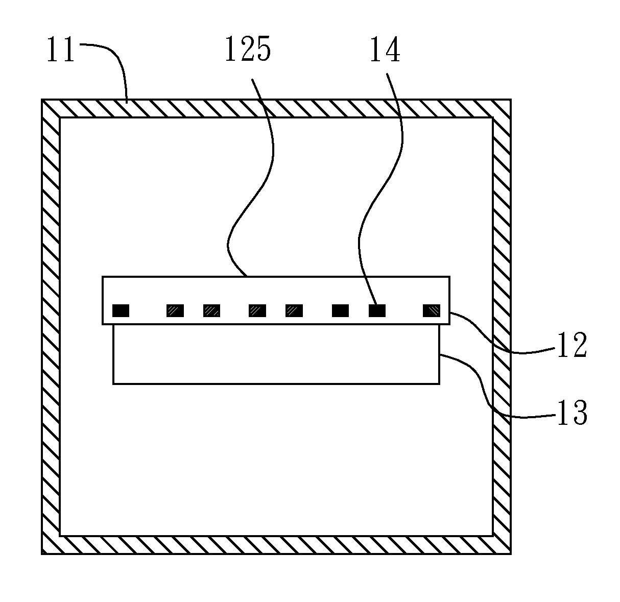
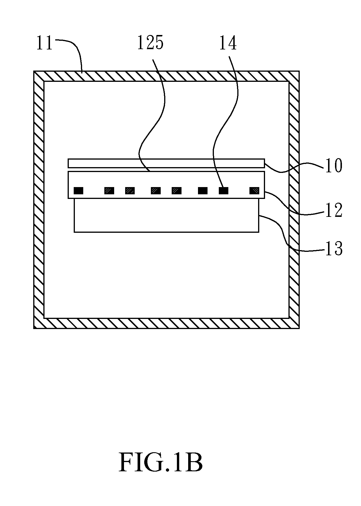
[0026]FIG. 1A shows a cross-sectional sketch of an atmospheric controlled chamber capable of controlling workpiece temperature according to one embodiment of the present invention. The experimental atmospheric controlled chamber includes a chamber wall 11, a support assembly 12, a heat-transfer assembly 13, and at least one thermopile device 14. FIG. 1B shows the condition that a workpiece 10 is held inside the atmospheric controlled chamber present on FIG. 1A.

[0027]The chamber wait 11 surrounds a space, and has one or more openings (not shown in the figure for brevity) disposed on different portions of the chamber wall 11, so that the workpiece 10 may be transferred into the space and / or transferred away from the space. The support assembly 12 is located in the space and is capable of holding the workpiece 10 over a specific (e.g., special, or predetermined) surface 125 of the support assembly 12. The workpiece 10 to be processed in, stored in and / or transferred through the atmosph...


PUM


Abstract

An atmospheric controlled chamber includes a support assembly capable of holding a workpiece over a specific surface of the support assembly, a heat-transfer assembly located close to the support assembly and capable of transferring heat to and from the exterior of the chamber, and at least one thermopile device disposed in the support assembly. The thermopile device(s) is configured to transfer heat between the specific surface (or viewed as the held workpiece) and the heat-transfer assembly. A gas assembly is optionally surrounded by the chamber wall and capable of ensuring the existence and controlling the pressure of an essentially static gas between the held workpiece and the specific surface, wherein the gas is used as a thermal medium for conducting heat. The thermopile device acts as an efficient heat pump, so as to provide extra lower/higher workpiece temperature, a greater cooling/heating rates, and more flexible rate control.

Description

BACKGROUND OF THE INVENTION[0001]1. Field of the Invention[0002]The present invention generally relates to heating and cooling a workpiece in an atmospheric controlled chamber and, more particularly, to the application of a thermopile device in an atmospheric controlled chamber for achieving one or more of lower / higher workpiece temperatures, greater cooling / heating rates, and greater flexibility in the control of cooling / heating rates.[0003]2. Description of Related Art[0004]Generally speaking, a workpiece (e.g., a semiconductor wafer, a glass plate, or other plate-like object) can be processed to fabricate different devices, such as an integrated circuit, a memory, a liquid crystal display (LCD), a solar cell, and so on. Different processes sometimes require different processing environments. As room temperature and an atmospheric environment typically surround machines used for processing the workpiece, the workpiece is sometimes treated (e.g., cooled or heated) in an atmospheric...

Claims


Application Information

Patent Timeline
IPC IPC(8): F25B21/02
CPCF25B21/02H01L21/67201H01L21/67109Y02P70/50
Inventor MCRAY, RICHARD F.
Owner ADVANCED ION BEAM TECHNOLOGY INC
Why Eureka
Try Eureka