Magnetic circuit, power-supplying device and power-receiving device for non-contact charging apparatus, and non-contact charging apparatus

a technology of power supply device and power supply device, which is applied in the direction of inductance, core/yoke, transportation and packaging, etc., can solve the problems of low power transmission efficiency, inability to align both marks in the dark, and failure to have a common power supply device for various power supply device, etc., to achieve excellent usability and reduce power transmission efficiency

Active Publication Date: 2012-12-20
HITACHI METALS LTD
View PDF3 Cites 76 Cited by
  • Summary
  • Abstract
  • Description
  • Claims
  • Application Information

AI Technical Summary

Benefits of technology

[0008]Accordingly, an object of the present invention is to provide a non-contact charging apparatus capable of surely positioning a secondary coil of a power-receiving device to a primary coil of a power-supplying device without substantially suffering from decrease in power transmission efficiency, thereby having excellent usability, and a magnetic circuit, a power-supplying device and a power-receiving device used therein.

Problems solved by technology

In this system, however, a power-supplying device should have a power-supplying surface adapted to each power-receiving device, failing to have a common power-supplying device for various power-receiving devices.
In this apparatus, however, each chargeable equipment should be provided with a center mark in advance, undesirable from the viewpoint of design, and the aligning of both marks cannot be conducted in the dark.
Because the magnetically saturated portion of the coil yoke has drastically decreased permeability, it fails to act as a yoke sufficiently, resulting in low power transmission efficiency.
In addition, the thin, L-shaped permanent magnet is difficult to produce by a rare-earth magnet, and easily broken during handling.
If the thin, L-shaped permanent magnet were formed, for instance, by a rubber magnet, sufficient magnetic power would not be obtained, resulting in poor positioning accuracy.

Method used


Image

  • Magnetic circuit, power-supplying device and power-receiving device for non-contact charging apparatus, and non-contact charging apparatus
  • Magnetic circuit, power-supplying device and power-receiving device for non-contact charging apparatus, and non-contact charging apparatus
  • Magnetic circuit, power-supplying device and power-receiving device for non-contact charging apparatus, and non-contact charging apparatus

Examples


example 1

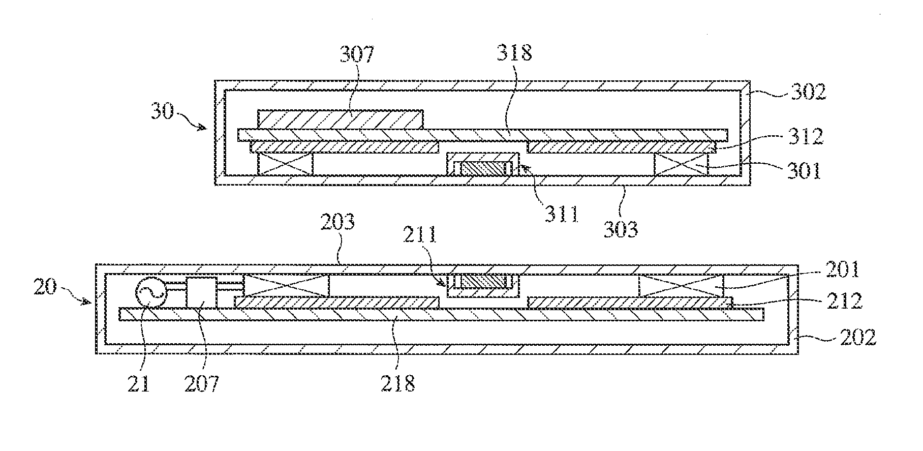
[0072]A non-contact charging apparatus with the structure shown in FIG. 1 having the following dimensions was produced for magnetic analysis.

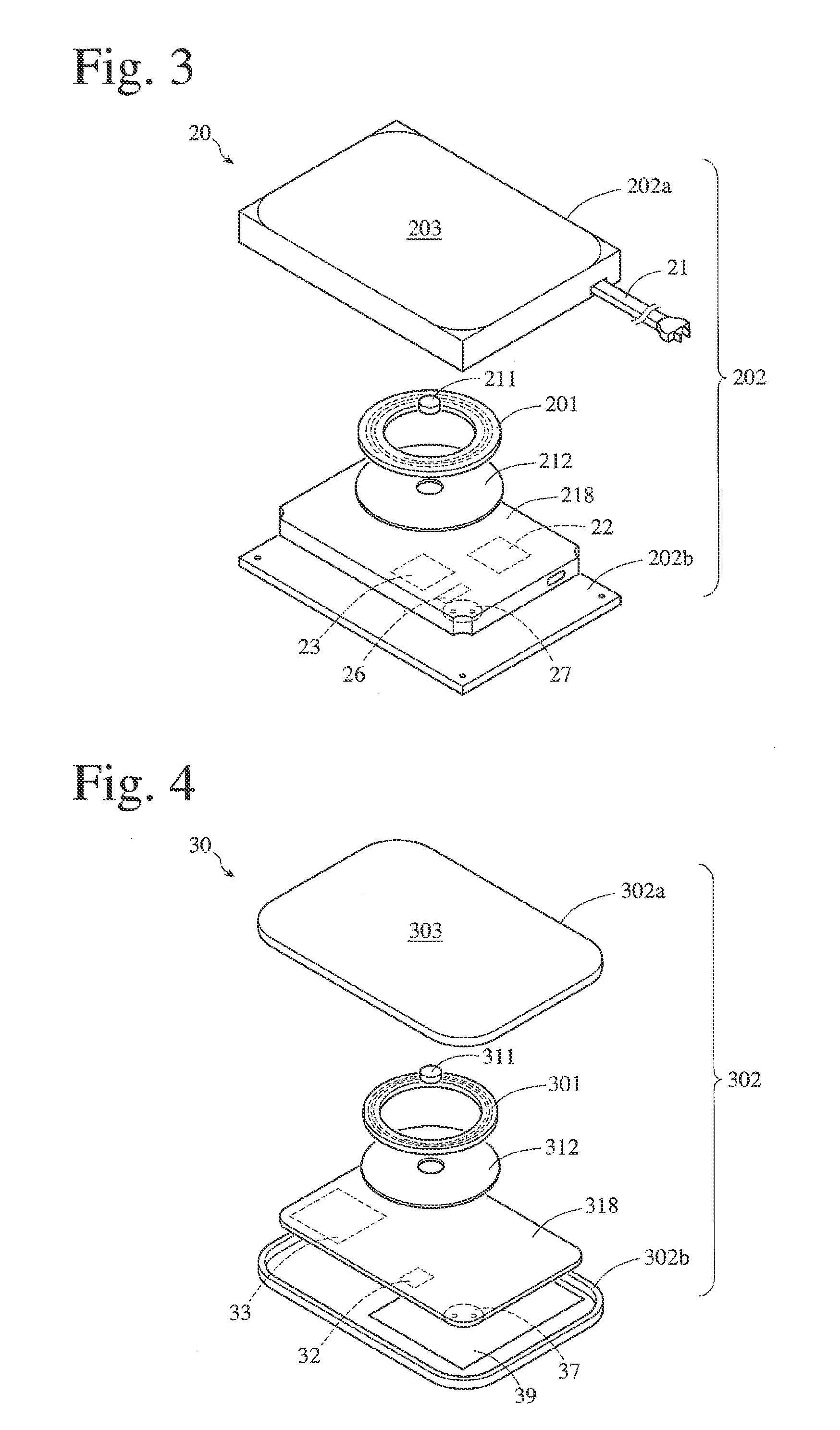
[0073](1) Power-Supplying Device

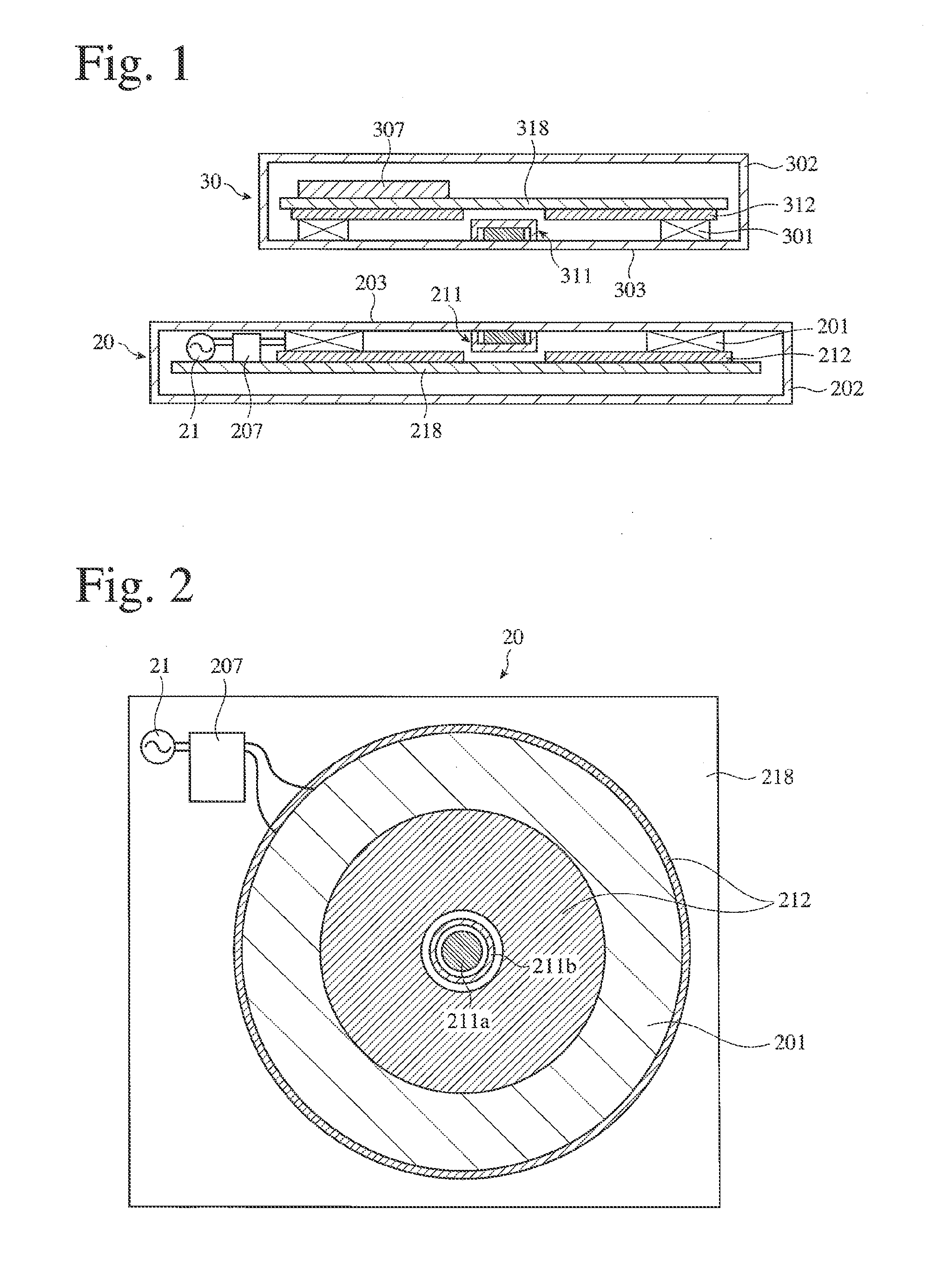
[0074]A primary coil 201 was concentrically adhered to a doughnut-plate-shaped coil yoke 212, and a magnetic attraction means 211 shown in FIG. 6(a) is disposed concentrically in a center hole of the coil yoke 212 to produce a power-supplying device 20 shown in FIG. 1. The primary coil 201 was formed by 20 turns of a copper wire having a diameter of 0.5 mm, with an inner diameter of 15 mm, an outer diameter of 35 mm and a thickness of 1 mm. The doughnut-plate-shaped coil yoke 212 having an inner diameter of 10 mm and an outer diameter of 40 mm was constituted by laminating two 20-μm-thick, Fe-based, nanocrystalline alloy ribbons (“FINEMET FT1” available from Hitachi Metals Ltd.), both surfaces of which were laminated with 50-μm-thick polyethylene terephthalate (PET) films. The magnetic attraction means 211 was co...

example 2

[0079]In the non-contact charging apparatus shown in FIG. 8, the relation between the outer diameter of the magnetic attraction means 311 and a magnetic flux density inside the coil yoke 312 was obtained by magnetic field analysis. The primary coil 201 was formed by 16 turns of a copper wire having a diameter of 0.5 mm, with an inner diameter of 17 mm, an outer diameter of 36 mm and a thickness of 1.0 mm, and the secondary coil 301 was formed by 8 turns of a copper wire having a diameter of 0.5 mm wire, with an inner diameter of 22 mm, an outer diameter of 32 mm and a thickness of 0.5 mm. The doughnut-plate-shaped coil yoke 212 having an inner diameter of 10 mm, an outer diameter of 40 mm and a thickness of 1 0 mm was formed by Mn—Zn ferrite. The doughnut-plate-shaped coil yoke 312 having an inner diameter of 10 mm and an outer diameter of 35 mm was constituted by laminating two 20-μm-thick, Fe-based, nanocrystalline alloy ribbons (“FINEMET FT1” available from Hitachi Metals Ltd.) v...

example 3

[0082]A non-contact charging apparatus shown in FIG. 10 was investigated with respect to the relation between a magnetic gap width between a magnetic attraction means and a coil yoke and the power transmission efficiency of the non-contact charging apparatus.

[0083](1) Power-Supplying Device

[0084]A coil yoke 212 formed by a ferrite disc having an outer diameter of 40 mm and a thickness of 1 mm was fixed onto a resin substrate 218. Concentrically disposed on the coil yoke 212 as a primary coil 201 was a resin-coated flat coil having an outer diameter of 40 mm, an inner diameter of 20 mm and a thickness of 0.5 mm and comprising 16 turns of a copper wire having a diameter of 0.5 mm. As a magnetic attraction means 211, a disc-shaped permanent magnet (surface magnetic flux density=150 mT) having an outer diameter of 15 mm, thickness 1.5 mm and a thickness of 0.5 mm was disposed concentrically with the primary coil 201. A front surface of the magnetic attraction means 211 and a front surfa...


PUM

PropertyMeasurementUnit
total thicknessaaaaaaaaaa
diameteraaaaaaaaaa

Abstract

A magnetic circuit for a non-contact charging apparatus comprising a coil, a coil yoke disposed on the rear surface side of the coil, and a magnetic attraction means disposed in a hole of the coil yoke with a magnetic gap in plane and/or thickness directions.

Description

FIELD OF THE INVENTION[0001]The present invention relates to a non-contact charging apparatus capable of surely positioning a secondary coil of a power-receiving device to a primary coil of a power-supplying device without substantially suffering from decrease in power transmission efficiency, and a magnetic circuit, a power-supplying device and a power-receiving device used therein.BACKGROUND OF THE INVENTION[0002]Recently, small information communications equipments such as mobile phones, etc. are getting high performance and high functions, and web terminals, music players, etc. are required to be continuously usable for a long period of time. These small information communications equipments and electronic equipments use secondary batteries such as lithium ion batteries, etc. as power sources.[0003]Methods for charging secondary batteries include contact charging systems and non-contact charging systems. The contact charging systems are systems of charging electricity by bringin...

Claims


Application Information

Patent Timeline
Patent Type & Authority Applications(United States)
IPC IPC(8): H01F38/14H02J7/00
CPCH02M3/33553H01F2003/103H01F38/14H01F3/10
Inventor ITABASHI, HIROMITSUMORIYAMA, YOSHIYUKI
Owner HITACHI METALS LTD
Why Eureka
Try Eureka