
Controlled randomized porous structures and methods for making same

a porous structure, controlled technology, applied in the field of porous structures, can solve the problems of consuming large amounts of energy in conventional metal foam fabrication processes, unable to provide the desired strength to serve as weight bearing structures in many medical implants, and forming undesirable metal compounds in metal foams, etc., to achieve the effect of improving strength

Active Publication Date: 2012-12-20
SMITH & NEPHEW INC
View PDF1 Cites 60 Cited by
  • Summary
  • Abstract
  • Description
  • Claims
  • Application Information

AI Technical Summary

Benefits of technology

[0014]One objective of the invention is to provide porous biocompatible structures suitable for use as medical implants that have improved strength for weight bearing purposes and porosity for tissue in-growth structures.
[0017]Another objective of the invention is to provide porous biocompatible structures suitable for use as medical implants having a controlled, yet random arrangement of struts and nodes for improved performance characteristics.
[0020]Yet another objective of the invention is to provide methods for providing a seamless fit between structures that are joined together, regardless of whether the structures are identical or not.

Problems solved by technology

While metal foams formed by such conventional methods provide good porosity, they may not provide the desired strength to serve as weight bearing structures in many medical implants.
Further, the processes used to form metal foams may lead to the formation of undesirable metal compounds in the metal foams by the reaction between the metal and the PFA.
Conventional metal foam fabrication processes also consume substantial amounts of energy and may produce noxious fumes.
That is, the conventional structure configurations lack directional strength and compensate for the weakness by making struts thicker, thereby decreasing the porosity, and conversely, a conventional structure with the desired porosity often lacks the desired strength because of the thinner struts.
There are no methods and / or products currently available that provide both the improved strength, improved porosity, and improved connectivity.
Further, trabecular bone structures are non-uniform and random in appearance on a micro-scale.
These methods, however, are limited because they typically require manual manipulation of the struts, i.e., solid space, of one unit to match up with another unit to build a scaffold of desired dimensions.
If the struts of the units do not match up, the integrity of the structure may be compromised if it has too many loose struts.
Similarly, a randomized structure with poorly oriented struts may have poor distribution of residual stresses due to the manufacturing method resulting in warped or inaccurate parts.
Otherwise, building a scaffold from complex randomized initial units would be too time consuming and costly, particularly in computation expenses.
Further, an additional drawback to randomizing an existing uniform structure is potentially making the structure weaker due to the unanticipated changes in the properties of the structure resulting from changes in the modulus and direction during the randomization process.
However, relatively few and simple shapes are employed within the unit tile due to the complexity of matching these tiles together.
Further, as a result of the deficiencies of metal foam implants and implants fabricated using conventional DMF methods, some medical implants require multiple structures, each designed for one or more different purposes.

Method used


Image

  • Controlled randomized porous structures and methods for making same
  • Controlled randomized porous structures and methods for making same
  • Controlled randomized porous structures and methods for making same

Examples


Embodiment Construction

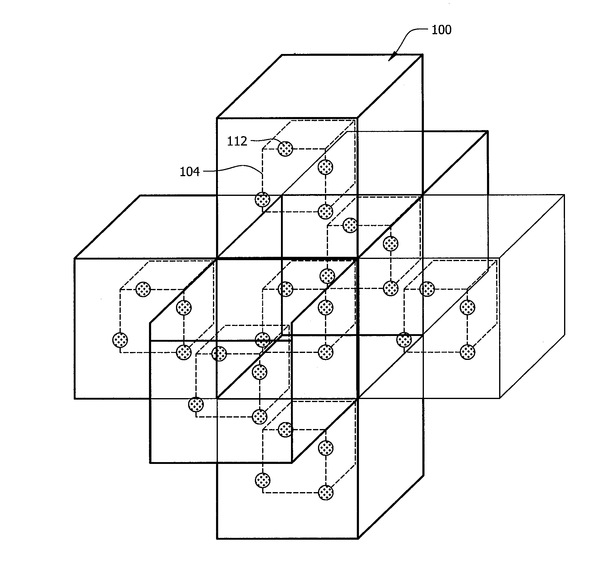
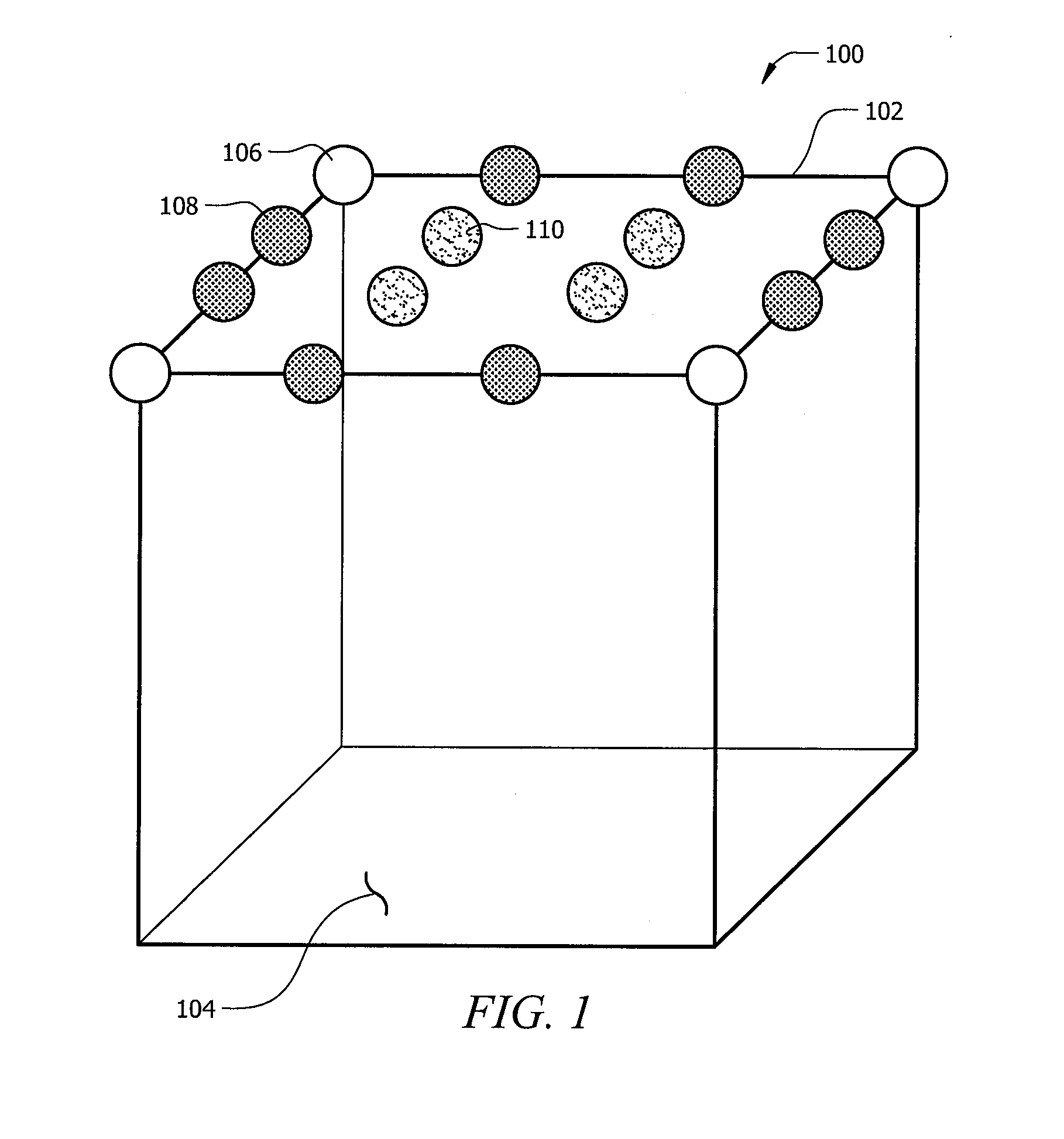
[0070]The present disclosure provides for methods to fabricate porous structures with improved strength, porosity, and connectivity. Preferably, the improved porous structures of the present invention is formed by using a free-from fabrication method, including rapid manufacturing techniques (RMT) such as direct metal fabrication (DMF). Typically in RMT or free-form fabrication, a model, or calculations defining the desired structure, or a computer readable file of the desired structure is provided to a computer-aided machine or apparatus that has an energy source such as a laser beam to melt or sinter powder to build the structure one layer at a time according to the provided model.

[0071]For example, RMT is an additive fabrication technique for manufacturing objects by sequential delivering energy and / or material to specified points in space to produce that part. Particularly, the objects can be produced in a layer-wise fashion from laser-fusible powders that are dispensed one laye...


PUM

PropertyMeasurementUnit
porositiesaaaaaaaaaa
threshold angleaaaaaaaaaa

Abstract

Improved randomized porous structures and methods of manufacturing such porous structures are disclosed. The scaffold of the porous structures are formed from by dividing the space between a plurality of spatial coordinates of a defined volume, where the plurality of spatial coordinates have been moved in a random direction and a random finite distance according to a predetermined randomization limit.

Description

[0001]The present application claims the benefit of U.S. Provisional Patent Application No. 61 / 260,811, filed Nov. 12, 2009 and entitled “Controlled Randomization of Porous Structures for Medical Implants,” the disclosure of which is incorporated by reference herein in its entirety.FIELD OF INVENTION[0002]The present invention generally relates to porous structures suitable for medical implants, and more particularly to porous structures suitable for medical implants that have improved combinations of strength, porosity and connectivity and methods for fabricating such improved porous structures.BACKGROUND[0003]Certain medical implants and orthopedic implants require strength for weight bearing purposes and porosity to encourage bone / tissue in-growth. For example, many orthopedic implants include porous sections that provide a scaffold structure to encourage bone in-growth during healing and a weight bearing section intended to render the patient ambulatory more quickly. For example...

Claims


Application Information

Patent Timeline
Patent Type & Authority Applications(United States)
IPC IPC(8): A61L27/56B22F3/11B29C67/20
CPCA61L27/56B33Y80/00Y10T428/249953A61L2430/02A61F2/02B22F10/85B33Y50/00G06F30/10A61L27/30A61L2420/02
Inventor LANDON, RYAN L.AGNIHOTRI, AASHIISHGILMOUR, LAURA J.SHARP, JEFFREYWINEBARGER, RANDY C.
Owner SMITH & NEPHEW INC
Learn More