Accelerator system stabilization for charged particle acceleration and radiation beam generation

a technology of accelerator system and charged particle, which is applied in the direction of accelerators, electrical devices, etc., can solve the problems of change in radiation beam energy and dose output, inability to turn the x-ray beam, and various sources of potential instability, and achieve fast frequency locking and stable radiation beam

Active Publication Date: 2012-12-27
VAREX IMAGING CORP
View PDF6 Cites 52 Cited by
  • Summary
  • Abstract
  • Description
  • Claims
  • Application Information

AI Technical Summary

Benefits of technology

[0016]Embodiments of the present invention allow at least certain components of the accelerator system to transition from their “beam-off” thermal equilibrium state to their “beam-on” thermal equilibrium state in a warm-up time period prior to the acceleration of injected charged particles and radiation beam generation, thereby improving stability of the accelerated charged particles and radiation beam.
[0020]In one example of an embodiment, an electric power supply provides electric power to the RF power components (the RF power supply, RF network, and accelerator), without providing electric power to the charged particle source. The RF power components can therefore warm up before particle acceleration and radiation generation, minimizing transition times between beam off / on thermal equilibrium states of the RF power components.
[0023]It has also been found that there may be a small difference between the accelerator's resonance frequency with and without particle injection. In accordance with another embodiment of the invention, at or near an end of a warm up period and prior to a start of beam generation in the beam-on time period, the AFC adjusts the RF source frequency to match an expected resonance frequency of the accelerator during the beam-on time period. In one example of this embodiment, this may be done by adjusting the RF source frequency to the actual resonance frequency of the accelerator plus a delta (Δ) representing the expected difference, in a time period between a last warm-up electric power pulse and a first beam-on electric power pulse, for example. By the time the first beam-on electric power pulse is delivered, the AFC returns to matching the RF source frequency to the actual resonance frequency of the accelerator. When particle acceleration and radiation beam generation starts in the beam-on time period, the RF source frequency will already be at or near the resonance frequency with particle injection, facilitating faster frequency locking and a more stable radiation beam.

Problems solved by technology

While acceptable for many applications, variations in dose and energy can negatively impact results in certain applications, which require more stable radiation dose and energy during the entire time the radiation beam is generated, starting from the initial generation of the radiation beam.
Due to radiation safety concerns and throughput requirements, it is not practical to turn the X-ray beam on, wait for it to stabilize, and then scan an object.
Various sources of potential instability may be present in an accelerator system.
A rapid transition from the RF-off thermal equilibrium state to the RF-on thermal equilibrium state may cause RF output power and / or frequency to vary when the beam is first turned on, resulting in a change in radiation beam energy and dose output.
Changes in insertion loss may lead to changes in RF power transmitted to the accelerator.
The accelerator is another potential source of instability, in part because the resonance frequency of the accelerator is susceptible to small temperature changes.
Changes in resonant frequency can cause a frequency mismatch with the RF source and RF network, increasing reflected RF power and weakening the electromagnetic field within the accelerator, resulting in reduced radiation beam energy.
However, the AFC may not fully compensate for frequency shifts in individual cavities.

Method used


Image

  • Accelerator system stabilization for charged particle acceleration and radiation beam generation
  • Accelerator system stabilization for charged particle acceleration and radiation beam generation
  • Accelerator system stabilization for charged particle acceleration and radiation beam generation

Examples


Embodiment Construction

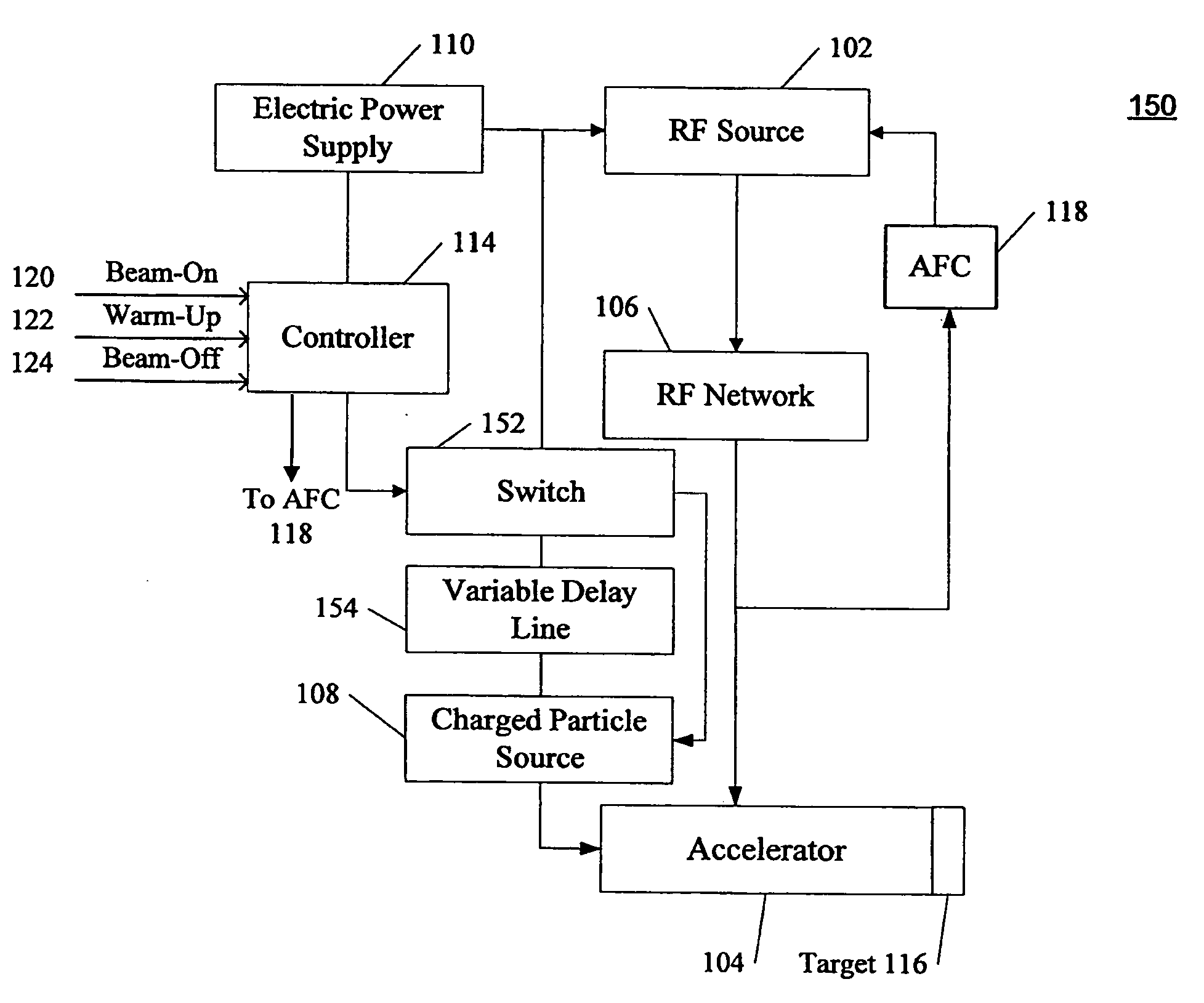
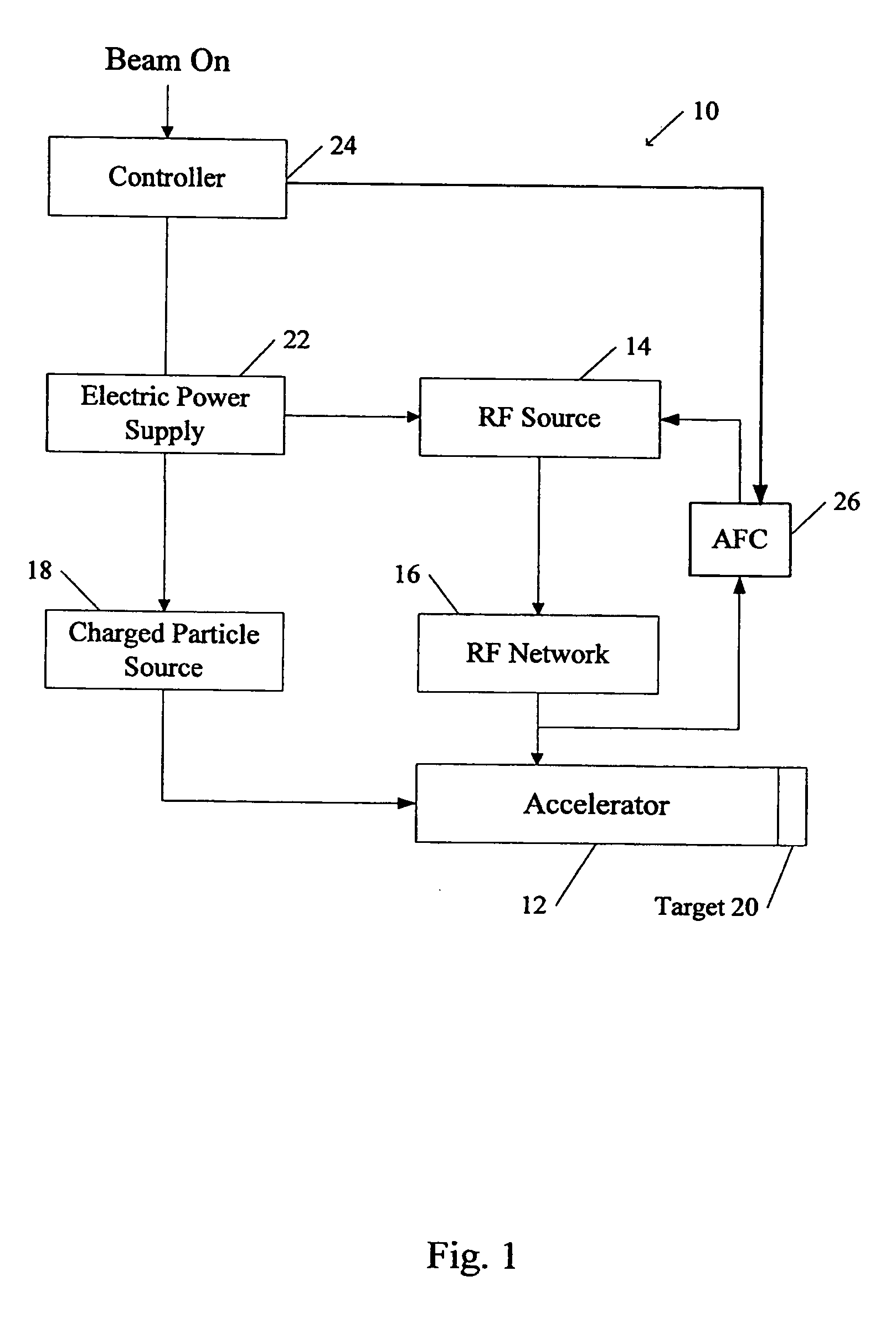
[0035]FIG. 4 is an example of an RF accelerator system 100 configured to generate more stable radiation beams, in accordance with one embodiment of the invention. In this example, an RF source 102 provides RF power to an RF accelerator 104 through an RF network 106, and the charged particle source 108 injects charged particles to the accelerator, as described above. An electric power supply 110 provides electrical power to the RF source 102 and the particle source 108. In accordance with this embodiment, an on / off switch 112 is provided between the electric power source 110 and the particle source 108, enabling electric power to be provided to the RF source 102 without being provided to the particle source. A controller 114, such as a programmable logic controller, a microprocessor, or a computer controls the electric power source 110 and the on / off switch 112, in response to input signals from an operator and / or programming. A target 116 is provided for radiation generation. Automa...


PUM


Abstract

A method for generating stabilized particle acceleration by a radio-frequency (RF) accelerator is described, comprising operating the accelerator in a warm-up mode during a warm-up time period, without injecting charged particles or without accelerating injected charged particles, and operating the accelerator in a beam-on mode during a beam-on time period after the warm-up time period, to accelerate charged particles injected by the charged particle source. Automatic frequency control to match an expected frequency of the accelerator during the beam-on time period, prior to the start of the beam-on time period, for stability, is also described.

Description

FIELD OF THE INVENTION[0001]Charged particle accelerator systems and, more particularly, charged particle accelerator systems and methods for stabilizing charged particle acceleration and radiation beam generation.BACKGROUND OF THE INVENTION[0002]Radiation is widely used in interrogation and irradiation of objects, including people. Examples of interrogation include medical imaging, cargo imaging, industrial tomography, and non-destructive testing (NDT) of objects. Examples of irradiation include food irradiation and radiation oncology. Accelerated charged particles, such as protons, are also used in radiation oncology.[0003]Radio-frequency (“RF”) accelerators are widely used to accelerate charged participles and to produce radiation beams, such as X-rays. RF accelerator based radiation sources may operate in a pulsed mode, in which charged particles are accelerated in short pulses a few microsecond long, for example, separated by dormant periods. Some applications require a “steady...

Claims


Application Information

Patent Timeline
Patent Type & Authority Applications(United States)
IPC IPC(8): H05H7/02
CPCH05H2007/022H05H7/02
Inventor EATON, DOUGLAS W.CHEN, GONGYINFOX, TIMOTHY R.
Owner VAREX IMAGING CORP
Why Eureka
Try Eureka