
Thermal Metal Spraying Apparatus

Active Publication Date: 2013-01-03
COMAU LLC
View PDF7 Cites 21 Cited by
  • Summary
  • Abstract
  • Description
  • Claims
  • Application Information

AI Technical Summary

Benefits of technology

The present invention is a thermal metal spraying apparatus that can apply a metal coating to a workpiece while masking the sprayed metal from the untreated surfaces. The apparatus includes a shroud that can be translated between a position where the opening is not aligned with the spraying orifice and a position where the opening is aligned with the spraying orifice. A deflection insert is connected to the second end of the shroud for deflecting the metal coating away from the workpiece when the shroud is in the first position. The apparatus also includes a drive mechanism for linear movement of the shroud and a mechanical spline for preventing rotational movement of the shroud. An outer mask is provided for changing the longitudinal length and a manipulator is provided for positioning the shroud and torch spraying nozzle relative to the workpiece. A processing cell is provided for enclosing the manipulator, torch spraying nozzle, and the workpiece. The apparatus can apply metal spray to the workpiece while it is held in a workholding fixture.

Problems solved by technology

When utilizing the PTWA process, it is difficult to control the spray of the molten metal in industrial applications.
Spraying the unprotected surfaces with a coating is impractical on an industrial scale, as the coating must be applied and then removed after the PTWA process.
Hard-tooled, dedicated covers are also not practical, as they limit the flexibility associated with automated tooling and machinery.
In addition, neither of these processes provide for a highly accurate spray line or boundary between the treated surfaces and the non-treated surfaces of the workpiece.

Method used


Image

  • Thermal Metal Spraying Apparatus
  • Thermal Metal Spraying Apparatus
  • Thermal Metal Spraying Apparatus

Examples


Embodiment Construction

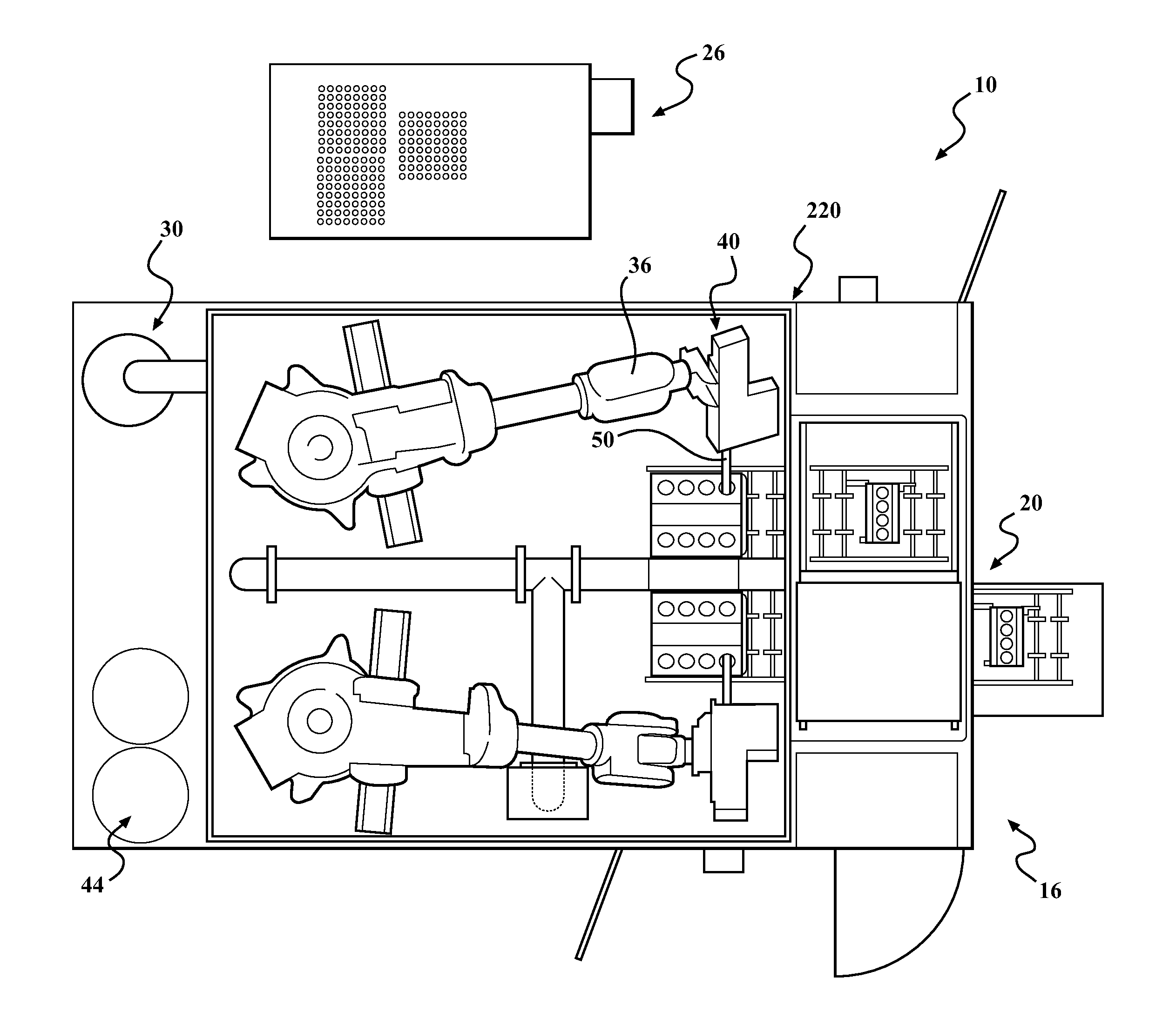
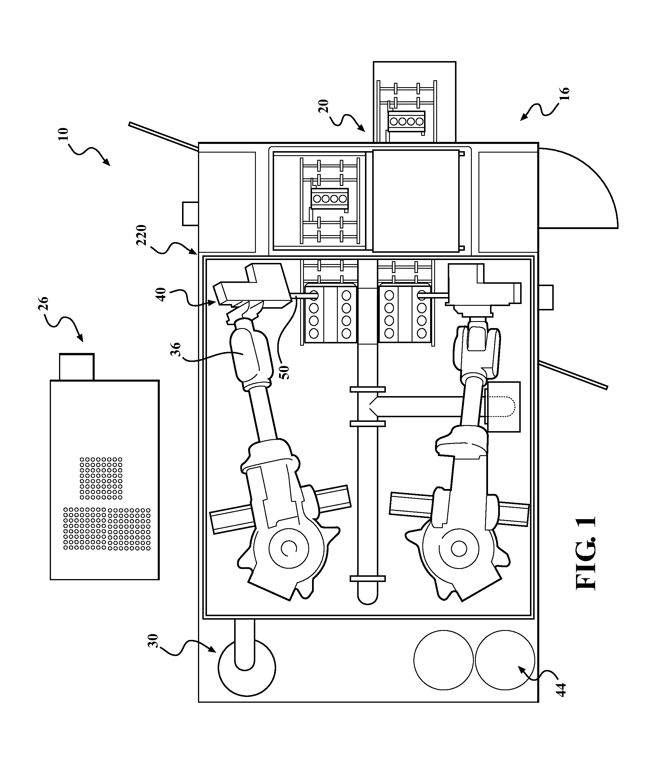
[0030]As illustrated in FIGS. 1-12, the present invention provides a thermal metal spraying apparatus that masks a workpiece from a metal coating spray.

[0031]Referring to FIG. 1, a thermal metal spraying apparatus 10 employs a metal spraying shroud assembly 50 as shown. In the example, the apparatus 10 includes a processing cell 16 having a part delivery system 20, a forced air device 26, a particle vacuum system 30, at least one manipulator or multi-axis programmed and controlled industrial robot 36 (two shown), a metal spraying torch assembly 40, and a wire feed system 44. The metal spraying torch assembly 40 is connected to the programmed robot 36 and is selectively movable in all three coordinate directions. The processing cell 16, the metal spraying torch assembly 40, and the metal spraying shroud assembly 50 may be used for coating an internal combustion engine block workpiece 46 with a metal spray 68 and is particularly useful in thermally spraying a thin metal film or coatin...


PUM

PropertyMeasurementUnit
Lengthaaaaaaaaaa
Angleaaaaaaaaaa
Diameteraaaaaaaaaa

Abstract

A thermal metal spraying apparatus for use with a thermal metal spraying torch for applying a metal coating to a workpiece through a torch spraying nozzle having a spraying orifice. The thermal metal spraying apparatus provides a substantially tubular shroud having a first end and a second end adaptable to concentrically receive the torch spraying nozzle. The shroud has an opening at the second end, wherein the opening is selectably alignable with the spraying orifice. A drive mechanism is connected to the shroud and is operable to translate the shroud between a first position, wherein the opening at the second end is not aligned with the spraying orifice, thereby preventing the spraying of the metal coating on the workpiece, and a second position, wherein the opening at the second end is aligned with the spraying orifice permitting the spraying of the metal coating toward the workpiece.

Description

CROSS-REFERENCE TO RELATED APPLICATIONS[0001]The subject application claims the priority of U.S. Provisional Patent Application Ser. No. 61 / 503,866, filed on Jul. 1, 2011.TECHNICAL FIELD[0002]The present invention relates to the field of thermal or plasma metal spraying for use in applying thin films and coatings, and in particular, a masking shroud for use with a thermal metal spraying torch that prevents the undesirable application of a metal spray or coating on a workpiece.BACKGROUND OF THE INVENTION[0003]The plasma transferred wire arc (“PTWA”) process is a particularly useful high-pressure plasma coating process capable of producing high-quality metallic coatings for a variety of applications, such as the coating of engine cylinder bores. In the PTWA process, a high-pressure plasma is generated in a small region of space at the exit of a plasma torch. A continuously-fed metallic wire impinges upon this region wherein the wire is melted and atomized by the plasma. High-speed gas...

Claims


Application Information

Patent Timeline
IPC IPC(8): C23C4/12
CPCB05B13/069B05B15/0443B05B15/0493C23C4/00F02F1/20B05B7/203B05B7/224B05B13/0636C23C4/12B05B1/28B05B12/40B05B12/36B05B12/26B05B12/20B05D1/02B05B13/0618
Inventor BROWN, THEODORE ROBERTGRAHAM, JOHN
Owner COMAU LLC
Features
  • Generate Ideas
  • Intellectual Property
  • Life Sciences
  • Materials
  • Tech Scout
  • Unparalleled Data Quality
  • Higher Quality Content
  • 60% Fewer Hallucinations
Learn More