Compact hybrid imaging lens assembly in an imaging reader

a hybrid imaging and reader technology, applied in the field of compact hybrid imaging lens assembly in imaging reader, can solve the problems of inability to implement alignment between glass lens and linear sensor array, inability to meet the requirements of electro-optical reading applications, etc., to achieve better thermal stability, reduce the size, weight and cost of the overall assembly, and improve the resistance to focal shift

Active Publication Date: 2013-01-03
SYMBOL TECH LLC
View PDF2 Cites 2 Cited by
  • Summary
  • Abstract
  • Description
  • Claims
  • Application Information

AI Technical Summary

Benefits of technology

[0008]In accordance with one aspect of this invention, a compact hybrid imaging lens assembly is provided in the reader, and is operative for capturing return illumination light through the presentation area from the target over the field of view, and for projecting the captured return illumination light onto the array during electro-optical reading of the target. The hybrid assembly includes a plastic lens for optical aberration correction. Preferably, the plastic lens has opposite surfaces of substantially the same curvature and has substantially none of the optical power of the imaging lens assembly. The hybrid assembly also includes a glass lens spaced away from the plastic lens along an optical axis. The glass lens has substantially all of the optical power of the imaging lens assembly for thermal stability. Preferably, the glass lens has opposite surfaces of different curvature.
[0010]Thus, the hybrid assembly is part-glass and part-plastic. Since virtually all the optical power is configured in the glass lens, and virtually no optical power is configured in the plastic lens, the hybrid assembly has better thermal stability and better resistance to focal shift with temperature variation as compared to an all-plastic lens assembly. The use of plastic lowers the size, weight and cost of the overall assembly and also lowers the number of optical components that comprise the assembly.
[0011]The use of plastic further enables alignment elements to be molded into the plastic lens. This could not be done with a glass lens. As noted above, these alignment elements enable the aperture stop to be aligned with the plastic lens, and also enable the plastic lens, as well as the entire assembly, to be aligned with the linear array. Thus, an asymmetrical aperture can be readily incorporated into the assembly. The aperture stop need no longer be molded into the holder, but instead, can be made as a quite thin separate component, and with a sharply defined edged aperture, to thereby realize improved optical performance.
[0012]In the hybrid assembly of this invention, the aperture is placed between the glass lens and the plastic lens, and provides optimum compensation of odd order aberrations (coma, astigmatism, distortion, etc.) since they tend to cancel each other. As a result, image distortion of less than 0.5% can be easily achieved. Image magnification stays nearly unchanged on and off the optical axis. Another benefit is that the physical size or diameter of the lenses can be minimized, thereby further reducing the overall weight and volume of the lens assembly.

Problems solved by technology

Yet, the all-glass lens design was heavier and more expensive to fabricate by machining than an all-plastic lens design.
Nevertheless, despite the lighter weight and lower fabrication cost of the plastic lens, the thermal instability and focal shift were unacceptable in many electro-optical reading applications.
In that event, the asymmetrical aperture needed to be aligned with the linear sensor array, and the all-glass lens assembly provided very little design flexibility in implementing alignment between a glass lens and the linear sensor array.
However, the one-piece molded aperture stop was a relatively thick element, and the edge of the aperture was not sharply defined.
As a result, the optical performance characteristics of the aperture stop were not fully realized.

Method used


Image

  • Compact hybrid imaging lens assembly in an imaging reader
  • Compact hybrid imaging lens assembly in an imaging reader
  • Compact hybrid imaging lens assembly in an imaging reader

Examples


Embodiment Construction

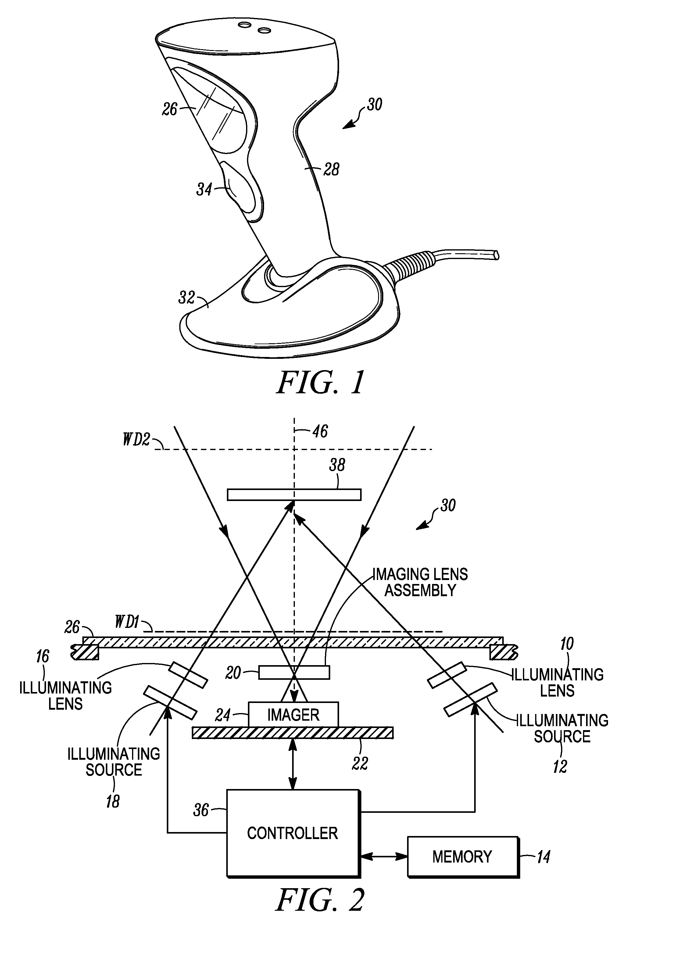
[0022]Reference numeral 30 in FIG. 1 generally identifies an imaging reader having a presentation area configured as a generally upright window 26 and a gun-shaped housing 28 supported by a base 32 for supporting the imaging reader 30 on a countertop. The imaging reader 30 can thus be used in a hands-free mode as a stationary workstation in which products are slid, swiped past, or presented to, the window 26, or can be picked up off the countertop and held in an operator's hand and used in a handheld mode in which the reader is moved, and a trigger 34 is manually depressed to initiate imaging of a target, especially one- or two-dimensional symbols, to be read at a distance from the window 26. In another variation, the base 32 can be omitted, and housings of other configurations can be employed. A cable, as illustrated in FIG. 1, connected to the base 32 can also be omitted, in which case, the reader 30 communicates with a remote host by a wireless link, and the reader is electricall...


PUM


Abstract

A compact hybrid imaging lens assembly captures return light from a target over a field of view of a linear array of image sensors of a solid-state imager, and projects the captured return light onto the array during electro-optical reading of the target. The assembly includes a plastic lens for optical aberration correction, a glass lens spaced away from the plastic lens along an optical axis, and an aperture stop between the lenses and having an asymmetrical aperture through which the optical axis extends. The glass lens has substantially all the optical power of the imaging lens assembly for thermal stability, and the plastic lens has substantially no optical power. A holder holds the lenses and the aperture stop away from the array. Alignment elements on the plastic lens align the asymmetrical aperture relative to the linear array.

Description

DESCRIPTION OF THE RELATED ART[0001]Solid-state imaging systems or imaging readers have been used, in both handheld and hands-free modes of operation, to electro-optically read symbol targets, such as one-dimensional symbols, particularly Universal Product Code (UPC) symbols, two-dimensional symbols, particularly Portable Data File 417 (PDF417) symbols, and non-symbol targets, such as driver's licenses, receipts, signatures, etc., the targets being associated with products to be identified and processed in supermarkets, warehouse clubs, department stores, retailers, libraries, factories, parcel deliveries, etc. In the hands-free mode, the products were typically slid or moved by a user across, or presented to, a presentation area, e.g., a reader window that faces the target. In the hand-held mode, the reader was held by the user, and the reader window was manually aimed at the target.[0002]The imaging reader included a solid-state imager with a sensor array of photocells or light se...

Claims


Application Information

Patent Timeline
Patent Type & Authority Applications(United States)
IPC IPC(8): G06K7/14H04N5/225
CPCG06K7/10831G06K7/10722
Inventor LIU, RONGTSI-SHI, DAVID
Owner SYMBOL TECH LLC
Why Eureka
Try Eureka