Antenna and wireless communication apparatus

a wireless communication and antenna technology, applied in the field of antennas, can solve the problems of difficult miniaturization of components, large problem of antenna size, bandwidth and gain restriction, etc., and achieve the effect of increasing the physical length of the antenna, small space, and reducing cos

Active Publication Date: 2013-01-03
KUANG CHI INTELLIGENT PHOTONIC TECH
View PDF2 Cites 16 Cited by
  • Summary
  • Abstract
  • Description
  • Claims
  • Application Information

AI Technical Summary

Benefits of technology

[0024]This design increases the physical length of the antenna equivalently, so an RF antenna operating at an extremely low frequency can be designed within a very small space. This can eliminate the physical limitation imposed by the spatial area when the conventional antenna op

Problems solved by technology

With advancement of the semiconductor manufacturing processes, requirements on the integration level of modern electronic systems become increasingly higher, and correspondingly, miniaturization of components has become a problem of great concern in the whole industry.
However, unlike integrated circuit (IC) chips that advance following the Moore's Law, radio frequency (RF) modules which are known as another kind of important components in the electronic systems are very difficult to be miniaturized.
However, some important indicators of the antenna such as the size, the bandwidth and the gain are restricted by the basic physical principles (e.g., the gain limit under the limitation of a fixed size, and the bandwidth limit).
The limits of these indicators make miniaturization of the antenna much more difficult than miniaturization of other components; and furthermore, due to complexity of analysis of the electromagnetic field of the RF component, even approximately reaching these limits represents a great technical challenge.
Meanwhile, as the modern electronic systems become more and more complex, the multi-mode services become increasingly important in wireless c

Method used


Image

  • Antenna and wireless communication apparatus
  • Antenna and wireless communication apparatus
  • Antenna and wireless communication apparatus

Examples


Embodiment Construction

[0046]Hereinbelow, the present disclosure will be detailed with reference to the attached drawings.

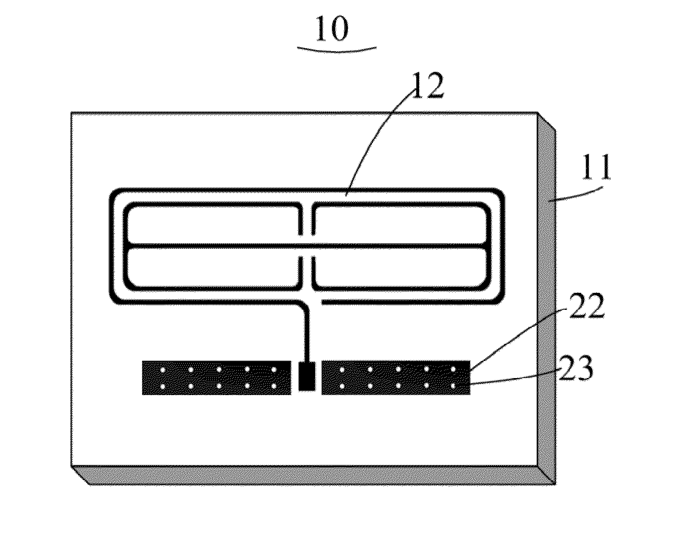
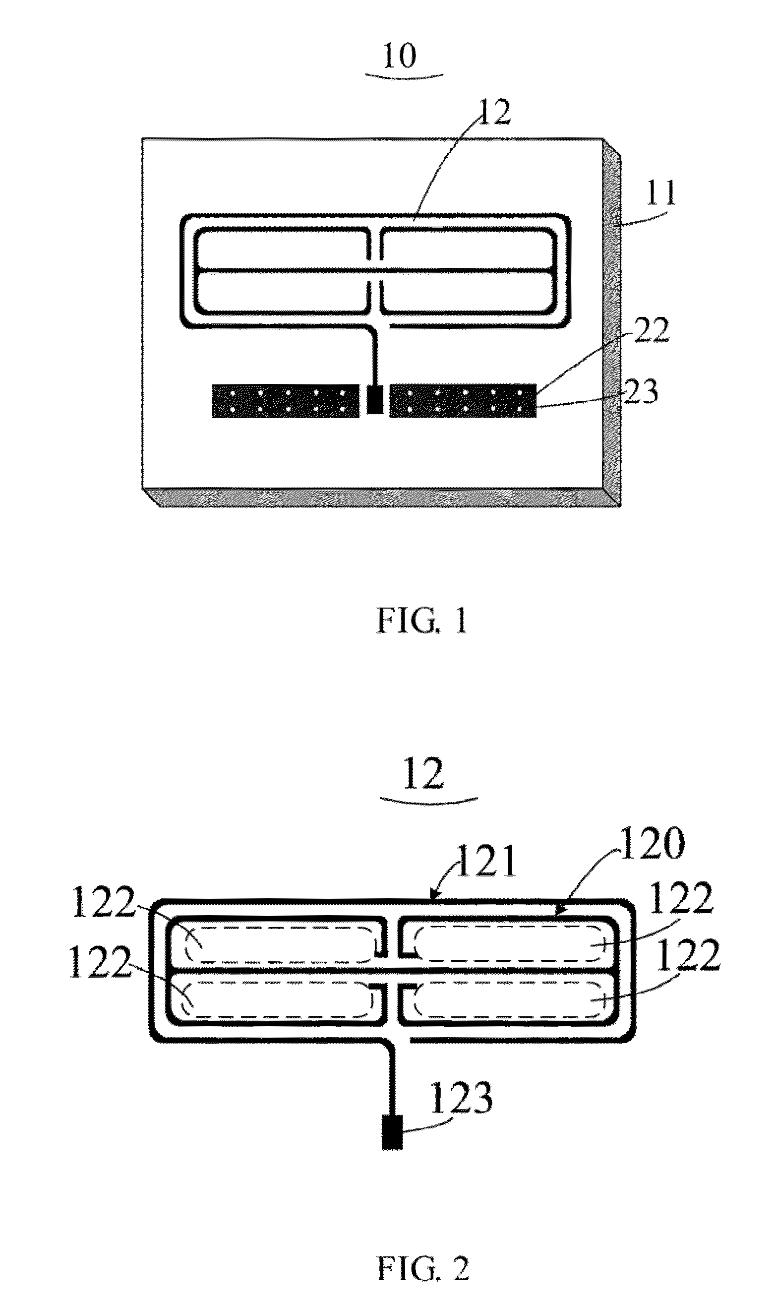
[0047]Referring to FIG. 1, there is shown a perspective view illustrating an embodiment of an antenna of the present disclosure. The antenna 10 comprises a medium substrate 11, and a metal structure 12 and grounding units 22 that are both attached on the medium substrate 11. Each of the grounding units 22 is a metal sheet, and has at least one metallization via 23 formed therein. In this embodiment, the metal structure 12 is attached on a surface of the medium substrate 11 of the antenna 10: the medium substrate 11 is provided with the grounding units 22 on two opposite surfaces thereof respectively;

[0048]and the medium substrate 11 is also formed with a via(s) (not shown) at a position(s) corresponding to the at least one metallization via 23, and the scattered grounding units 22 are electrically connected through the at least one metallization via 23 to form a common ground. In other...


PUM


Abstract

An antenna comprises a medium substrate and grounding units attached on the medium substrate. The antenna further comprises a metal structure attached on the medium substrate. The metal structure comprises an electromagnetic response unit, a metal open ring enclosing the electromagnetic response unit and a feeding point connected to an end of the metal open ring. The electromagnetic response unit comprises an electric-field coupling structure. This design increases the physical length of the antenna equivalently, so an RF antenna operating at an extremely low frequency can be designed within a very small space. This can eliminate the physical limitation imposed by the spatial area when the conventional antenna operates at a low frequency, and satisfy the requirements of miniaturization, a low operating frequency and broadband multi-mode services for the mobile phone antenna. Meanwhile, a solution of a lower cost is provided for design of the antenna of wireless communication apparatuses.

Description

FIELD OF THE INVENTION[0001]The present disclosure generally relates to the technical field of antenna, and more particularly, to an antenna and a wireless communication apparatus using the same.BACKGROUND OF THE INVENTION[0002]With advancement of the semiconductor manufacturing processes, requirements on the integration level of modern electronic systems become increasingly higher, and correspondingly, miniaturization of components has become a problem of great concern in the whole industry. However, unlike integrated circuit (IC) chips that advance following the Moore's Law, radio frequency (RF) modules which are known as another kind of important components in the electronic systems are very difficult to be miniaturized. An RF module mainly comprises a mixer, a power amplifier, a filter; an RF signal transmission component, a matching network and an antenna as key components thereof. The antenna acts as a transmitting unit and a receiving unit for RF signals; and the operation pe...

Claims


Application Information

Patent Timeline
IPC IPC(8): H01Q1/38
CPCH01Q9/42
Inventor LIU, RUOPENGXU, GUANXIONGFANG, NENGHUI
Owner KUANG CHI INTELLIGENT PHOTONIC TECH
Why Eureka
Try Eureka