
Frequency offset estimation scheme in scheduled based wireless system

a frequency offset and wireless receiver technology, applied in the field of wireless communication, can solve the problems of fsub>residual /sub>, fsub>distributed signal distortion, and recalculation of coarse+fine /sub>,

Active Publication Date: 2013-01-03
AVAGO TECH INT SALES PTE LTD
View PDF2 Cites 9 Cited by
  • Summary
  • Abstract
  • Description
  • Claims
  • Application Information

AI Technical Summary

Benefits of technology

The patent text discusses a method for estimating the frequency offset in wireless communication systems. The technical effect of this invention is to improve the accuracy of frequency offset estimation in wireless receivers, which can enhance the quality of service in high-throughput wireless data transmissions.

Problems solved by technology

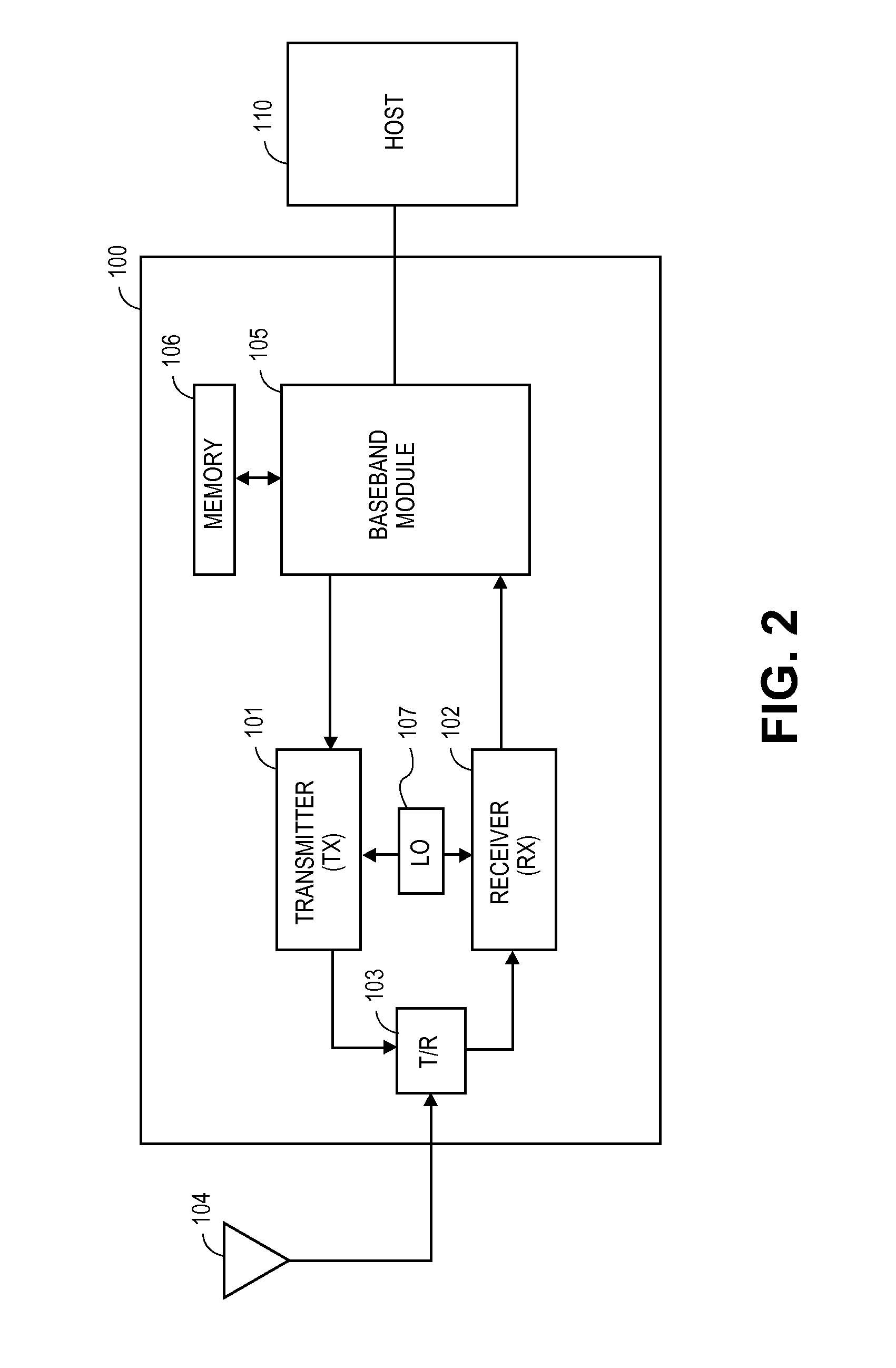
The frequency offset may be caused by a variety of factors, but two main causes are due to the mismatch between the transmitter local oscillator (LO) and the receiver LO, and the distortion of the transmitted signal in the channel during transmit.
A drawback of this approach is that Δfcoarse+fine is recalculated for each packet, even if the subsequent packet is from the same source as the previous packet.
Another drawback is that the Δfresidual is left uncompensated at the beginning of a packet, since the Δfresidual tracking does not commence until later in the packet.
However, in low SNR situations, the Δfresidual may be significant due to the Δfcoarse+fine accuracy degradation.
For systems operating in the 60 GHz frequency band, significant loss in link margin may occur as compared to similar systems operating at 2.4-5.8 GHz, or even lower frequency band, due to the significantly increased free space loss.
Large, uncompensated Δfresidual may reduce the chance of correctly decoding the PLCP Header, as well as the subsequent data.
Because the retransmission of corrupted data packets not only wastes valuable wireless channel time but also introduces additional packet delivery latency, wherein such excessive retransmission and buffering due to repeated failures can ruin the user experience.

Method used


Image

  • Frequency offset estimation scheme in scheduled based wireless system
  • Frequency offset estimation scheme in scheduled based wireless system
  • Frequency offset estimation scheme in scheduled based wireless system

Examples


Embodiment Construction

[0021]The embodiments of the present invention may be practiced in a variety of wireless communication devices that operate in a wireless network. The examples described herein pertain to devices that operate approximately within the 60 GHz Band, which is in the range of millimeter wave transmissions. However, the invention need not be limited to the 60 GHz Band. Furthermore, the examples described herein pertain to specific designations, such as a Service Period (SP). However, the invention need not be limited to such specific applications.

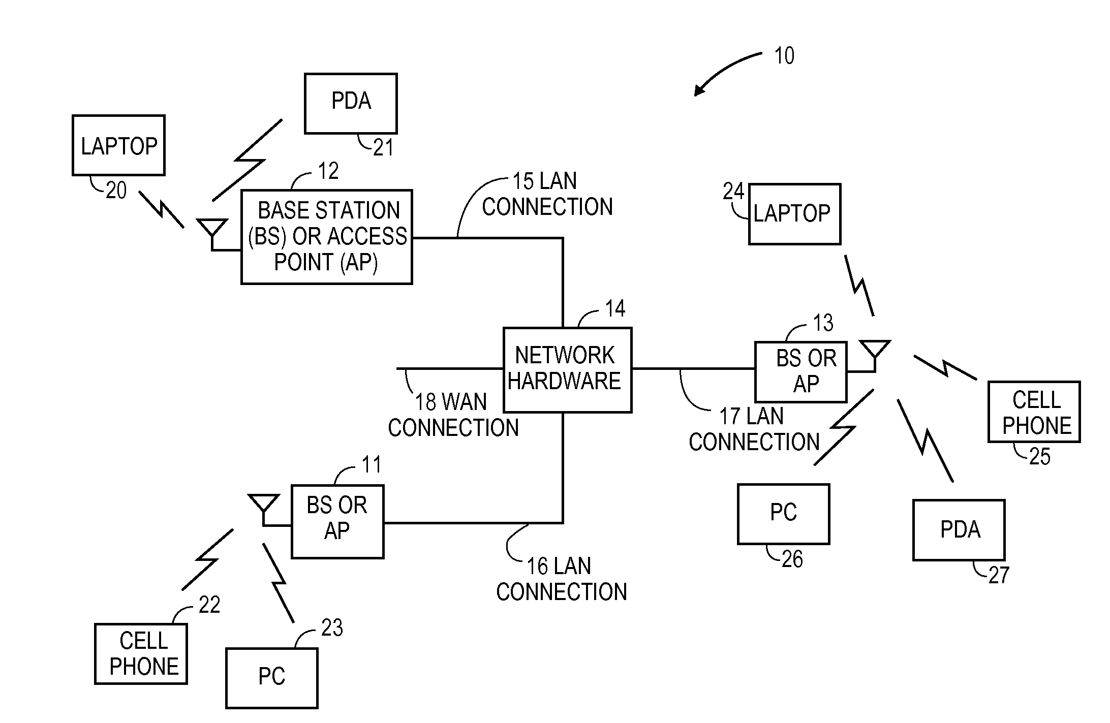
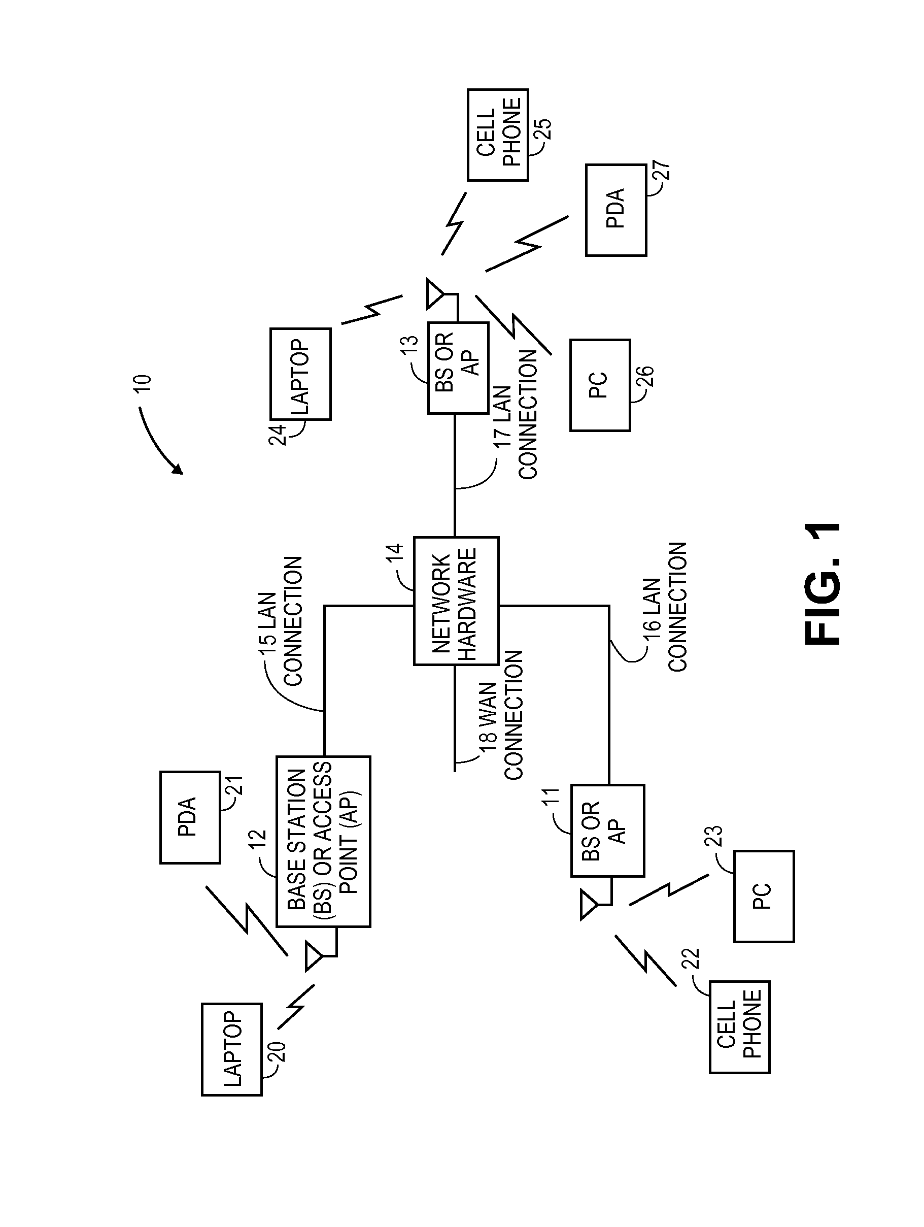
[0022]FIG. 1 illustrates one environment for practicing the present invention. FIG. 1 shows a communication system 10 that includes a plurality of base stations (BS) and / or access points (AP) 11-13, a plurality of wireless communication devices 20-27 and a network hardware component 14. The wireless communication devices 20-27 may be laptop computers 20 and 24, personal digital assistants 21 and 27, personal computers 23 and 26, cellular telephon...


PUM


Abstract

A technique to provide frequency offset estimation for packets transmitted during a service period allocated strictly for designated source and destination devices. The destination device obtains coarse and fine frequency offset estimation from the short and long preambles. A residual frequency offset is tracked for the data blocks and combined with the coarse and fine frequency offset to obtain a total frequency offset to apply to the data blocks. The total frequency offset value at the end of the first packet is saved and, instead of again estimating the coarse and fine frequency offset values with the short and long preambles of the second packet, the saved total frequency offset value is used as the initialization value to add to the residual frequency offset in the second packet. The saved offset value at the end of each packet becomes the initialization value for the subsequent packet.

Description

BACKGROUND OF THE INVENTION[0001]1. Technical Field of the Invention[0002]The embodiments of the invention relate to wireless communications and, more particularly, to frequency offset estimation in wireless receivers.[0003]2. Description of Related Art[0004]Various wireless communication systems are known today to provide links between devices, whether directly or through a network. Such communication systems range from national and / or international cellular telephone systems, the Internet, point-to-point in-home systems, as well as other systems. Communication systems typically operate in accordance with one or more communication standards or protocol. For instance, wireless communication systems may operate using protocols, such as IEEE 802.11, Bluetooth™, advanced mobile phone services (AMPS), digital AMPS, global system for mobile communications (GSM), code division multiple access (CDMA), local multi-point distribution systems (LMDS), multi-channel-multi-point distribution sys...

Claims


Application Information

Patent Timeline
IPC IPC(8): H04W24/00
CPCH04L27/2659H04L27/2675H04L27/266
Inventor XIE, HONGYUZHUANG, YUANMESE, MURATIBRAHIM, BRIMA
Owner AVAGO TECH INT SALES PTE LTD
Learn More