
Method for manufacturing battery electrode

a battery electrode and manufacturing method technology, applied in the manufacture of final products, electrode manufacturing processes, cell components, etc., can solve the problems of reducing battery performance, achieve the effect of reducing the amount of binder, reducing the amount of adhesive strength (adhesion), and reducing the amount of negative electrode mixtur

Active Publication Date: 2013-01-03
TOYOTA JIDOSHA KK
View PDF4 Cites 6 Cited by
  • Summary
  • Abstract
  • Description
  • Claims
  • Application Information

AI Technical Summary

Benefits of technology

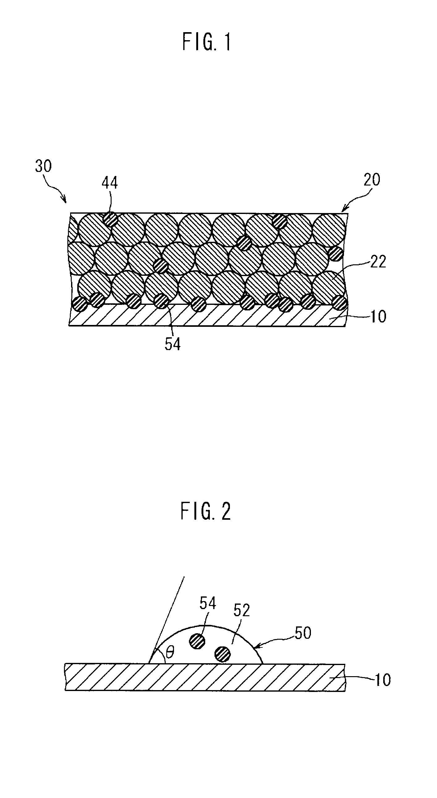
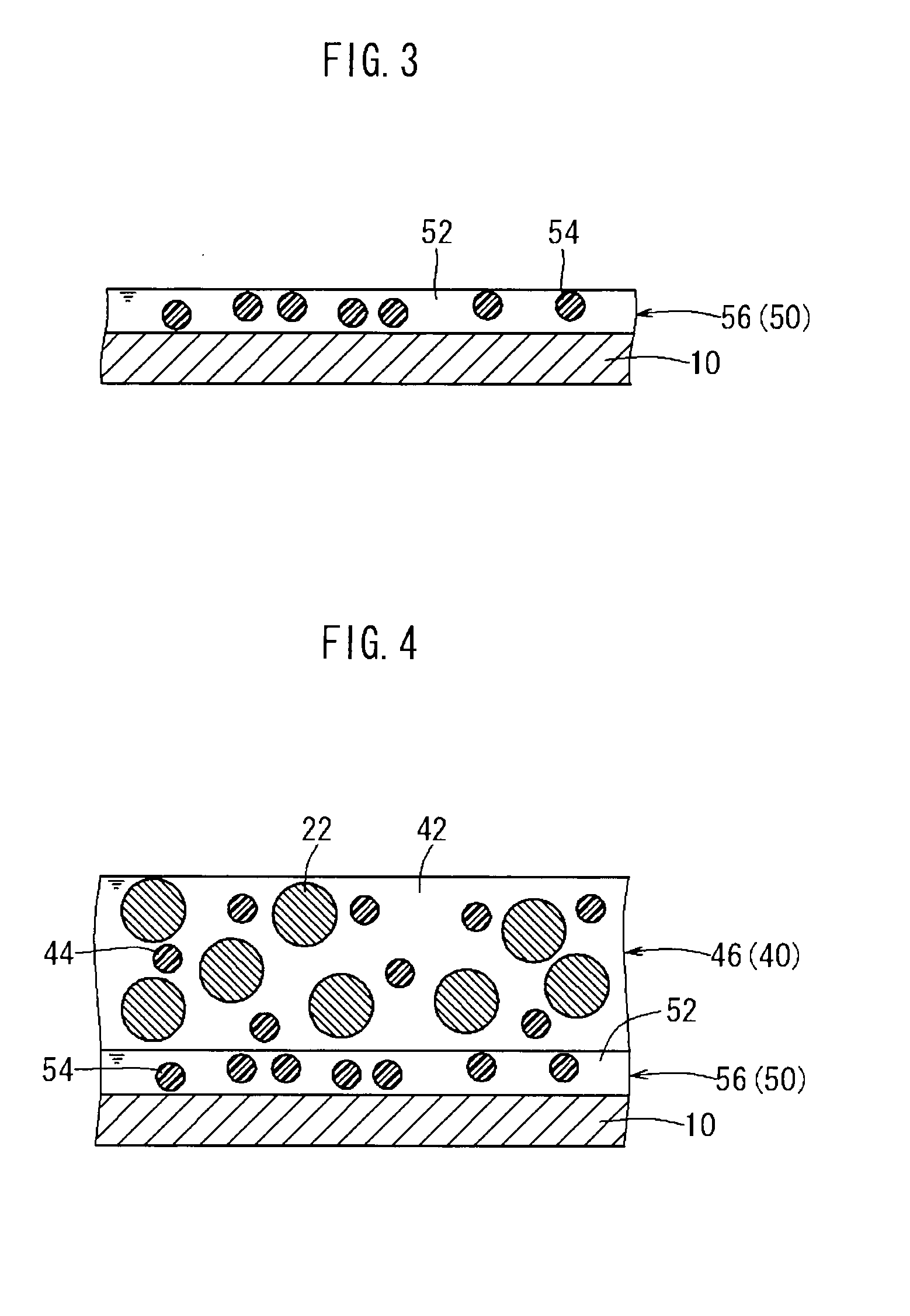
The present invention provides a method for manufacturing a battery electrode with improved adhesion between the current collector and the mixed material layer, resulting in a smooth and even surface. This is achieved by using a binder solution with a contact angle of 73° or less with the current collector surface, which increases the wettability of the binder solution and allows for a uniform thickness of the mixed material layer. The mixed material paste layer is deposited so that the applied edge of the mixed material paste layer protrudes farther outward than the applied edge of the binder solution layer, which improves the smoothness of the mixed material layer. The binder solution layer is formed to a thickness of 3 μm or less to further enhance the smoothness of the mixed material layer. The method also allows for rapid drying of the mixed material paste layer by setting a high drying speed. The battery constructed using the electrode exhibits superb battery performance.

Problems solved by technology

There is a problem, however because during the manufacture of the above negative electrode, when the mixed material paste containing the negative electrode active material powder and the binder is applied to the negative current collector and dried rapidly, a convection current develops during drying, and the binder close to the current collector rises and collects at the surface layer of the applied paste (i.e., the side opposite the current collector).
If the adhesive strength between the negative current collector and the negative electrode mixture decreases, during subsequent manufacturing steps (for example, the step of winding the negative electrode sheet and positive electrode sheet into a coiled configuration) and also during battery use the negative electrode mixture can rise off or peel away from the negative current collector, and that can become a factor that decreases battery performance.

Method used


Image

  • Method for manufacturing battery electrode
  • Method for manufacturing battery electrode
  • Method for manufacturing battery electrode

Examples


Embodiment Construction

[0030]An embodiment of the present invention is described below while referencing the drawings. In the following drawings, all parts and components with the same function are described by identical symbols. Moreover, the dimensional relationships (of length, width, height, etc.) in the drawings do not depict actual dimensional relationships. Furthermore, matters necessary for carrying out the present invention other than those specifically referred to in the description (e.g., the configuration and fabrication process of the electrode assembly featuring a positive electrode and negative electrode; the configuration and fabrication process the separator and electrolyte; common technology related to batteries and the configurations of other batteries, etc.) are understood to be matters of design for a person skilled in the art based on the prior art in this field.

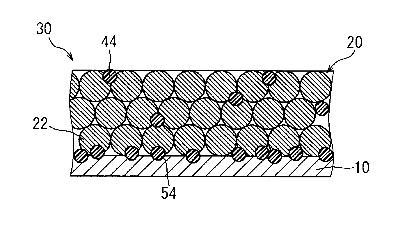
[0031]As illustrated in FIG. 1, the manufacturing method for an electrode disclosed herein is one for an electrode 30 havin...


PUM


Abstract

The present invention provides a method for manufacturing a battery electrode. This method comprises the steps of applying a binder solution 50 that contains a binder 54 and is adjusted so that the contact angle of the binder solution 50 with the surface of a current collector 10 is 73° or less, to form a binder solution layer 56; applying a mixed material paste 40 containing an active material 22 on top of the binder solution layer 56, to deposit both the binder solution layer 56 and a mixed material paste layer 46 on the current collector 10; and obtaining an electrode 30 in which a mixed material layer 20 is formed on the current collector 10, by drying the deposited binder solution layer 56 and mixed material paste layer 46 together.

Description

TECHNICAL FIELD[0001]The present invention relates to a method for manufacturing a battery electrode, and more particularly to a method for manufacturing a battery electrode having a configuration in which an electrode mixed material layer containing an electrode active material is retained on a current collector.BACKGROUND ART[0002]Lithium-ion batteries, nickel-metal hydride batteries, and other secondary batteries have become more important recently as a vehicle-mounted electrical power source, as well as a power source for personal computers and portable devices. In particular, it is expected that lithium secondary batteries, which offer both light weight and high energy density, can be preferably used as a high output electrical power source for vehicles. One typical configuration for such a secondary battery provides an electrode with a configuration in which a material capable of reversibly absorbing and desorbing lithium ions (electrode active material) is retained on a condu...

Claims


Application Information

Patent Timeline
IPC IPC(8): H01M4/64H01M4/04H01M4/139H01M4/1393H01M4/587
CPCY02E60/122H01M4/663H01M4/1393H01M4/133Y02E60/10H01M4/04H01M4/583H01M4/66H01M4/0404Y02P70/50
Inventor YAMAZAKI, NOBUYUKIUCHIDA, YOZO
Owner TOYOTA JIDOSHA KK
Learn More