Method for Detecting Foreign Object Damage in Turbomachinery

a technology for turbomachinery and foreign objects, applied in the direction of process and machine control, testing/monitoring control system, instruments, etc., can solve the problems of compromising engine operation and safety, loss of life or total loss of assets, lack of reliable instrumentation to provide, etc., and achieve cost reduction

Active Publication Date: 2013-01-03
PRIME PHOTONICS LC
View PDF1 Cites 18 Cited by
  • Summary
  • Abstract
  • Description
  • Claims
  • Application Information

AI Technical Summary

Benefits of technology

[0020]versatility—the system is compatible with metallic or nonmetallic blades, and whereby a single technology for many platforms reduces cost.

Problems solved by technology

Foreign Object Damage (FOD) to gas turbine engines can result when debris is ingested by the engine which can compromise engine operation and safety.
The worst case scenario for the current method of inspection is for a minor FOD event to have gone undetected, due to a lack of inspection based on schedule or failure to detect the damage, and then result in a later failure of the engine causing loss of life or total loss of the asset.
There is currently a lack of reliable instrumentation which can provide data about noncatastrophic FOD without an extended examination by a highly skilled technician.
Such a process becomes increasingly difficult as engines and airframes become more and more integrated, as the access to necessary points on the engine becomes limited.
Further, without knowing that a FOD event has occurred, there is no way to determine the optimal points in time at which an engine should be inspected.
This leads to the inefficient schedule-based maintenance approach where all engines, regardless of potential damage, are inspected on a regular basis in the hopes of identifying blade damage early so that it can be corrected before engine failure.
As a result, this constitutes a time consuming and very expensive approach toward obtaining the needed information.
A disadvantage of existing FOD detection systems is they often have complex hardware components leading to increased weight and implementation costs.
The approaches of such systems and methods lack one or more of reliability, accuracy, and sensitivity in detecting the presence of damaged blades.

Method used


Image

  • Method for Detecting Foreign Object Damage in Turbomachinery
  • Method for Detecting Foreign Object Damage in Turbomachinery
  • Method for Detecting Foreign Object Damage in Turbomachinery

Examples


example i

Turbine Blade Fingerprint Analysis

[0058]Blade damage can be categorized using a spectrum that ranges from cosmetic changes in the blade surface, increasing to minor levels of damage, then moderate damage, and ultimately rising to the level of severe blade damage potentially leading to or resulting in catastrophic engine failure. In some situations, damage even to a single blade if sufficiently severe, can cause cascading failure through the entire engine, leading to immediate engine inoperability.

[0059]Objects of the invention provide systems and methods capable of identifying many varied levels of turbine blade damage. The systems and methods of the present invention, however, are best suited for identifying intermediate levels of blade damage, including micro, minor, or moderate levels of blade damage. In the context of this invention, there is little value in identifying cosmetic changes, which are rarely important with respect to blade function, and little value in identifying c...

example ii

Blade Identification

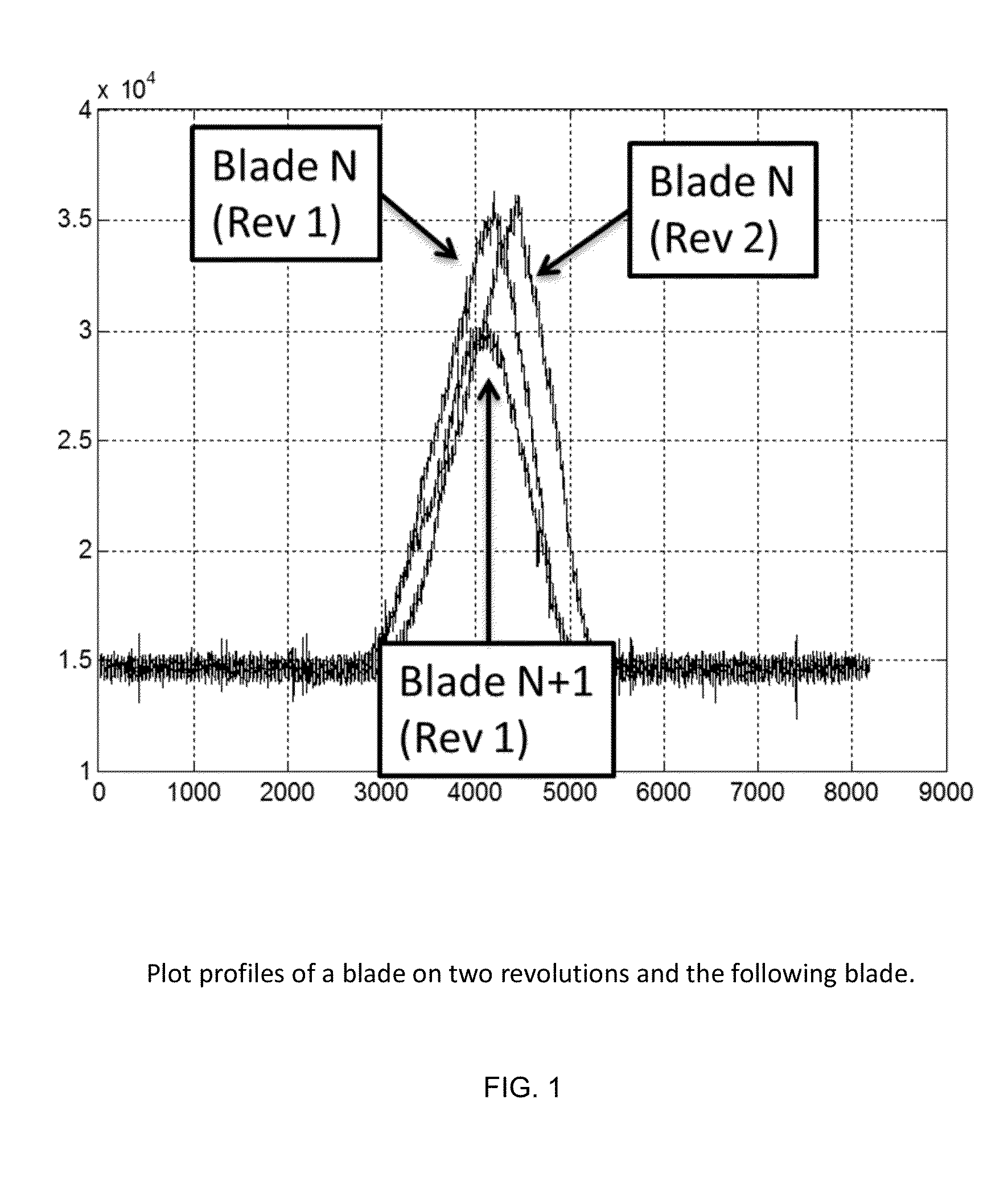
[0088]There are several related methods for performing blade identification. In embodiments, the data utilized is a time varying optical reflection obtained by observing the blade passing a fixed point, such as a fixed point on the engine case. This is illustrated in FIG. 5. The sensor and system described above is an ideal example of the type of sensor that can be used to generate this waveform.

[0089]In most cases the process is simplified by resampling the data into a non-time based sequence. This allows blade data sets to be compared even in cases where the rotor speed is changing between data sets. This can be thought of as being the rotor's global phase angle (0-360 degrees of angular offset relative to an arbitrary starting position), or done locally as a fraction of the local blade width.

[0090]Resampling approaches can include a method of determining the number of blades on the rotor and counting the amount of time required for that many blades to pass, tr...

example iii

Blade Damage Detection Based on Time of Arrival Analysis

[0095]Another method of the invention that can be used individually or in combination with the blade fingerprint and / or blade identification analyses described above is a method for detecting blade damage based on blade time of arrival analysis.

[0096]Accordingly, systems and methods of the invention are capable of collecting and deciphering large amounts of timing-related data relating to the blades, e.g., blades on a turbine rotor. In the context of this specification, blades disposed on a rotor has the same meaning as a rotor comprising blades whether the blades are attached to the rotor as a separate entity or whether the blades and the rotor comprise a single integral unit. In embodiments, this is accomplished by analyzing one or more aspects of the pulses reflected from the blades, such as pulse width, rise time, rising edge shoulder, rising edge duration, fall time, start of falling edge, number of local maxima and minima...


PUM


Abstract

The present invention relates to systems and methods for real-time health monitoring of engines to monitor turbomachinery blades during engine operation and report anomalous behavior and shape of the blades if it occurs, such as damage by FOD. The system comprises sensor(s) for obtaining a blade reflection profile from a blade passing by the sensor(s) during a revolution of the rotor in combination with a processor for performing timing calculations and/or fingerprint comparisons with reference data to identify a change in blade fingerprint relative to the reference data, which may indicate blade damage. Such systems can reduce operational costs, enhance safety and improve operational readiness by facilitating condition-based maintenance of engine rotors as opposed to schedule-based solutions. The invention can prevent the needless loss of life and assets caused by undetected minor levels of blade damage that may lead to unexpected catastrophic failure of an engine.

Description

CROSS-REFERENCE TO RELATED APPLICATIONS[0001]This application relies on the disclosure of and claims priority to and the benefit of the filing date of U.S. Provisional Application Nos. 61 / 520,948 and 61 / 520,953, filed Jun. 18, 2011, the disclosures of which are hereby incorporated by reference herein in their entireties.STATEMENT OF GOVERNMENT INTEREST[0002]This invention was supported by the U.S. Navy under Contract No. N68335-11-C-0061. The U.S. Government has certain rights in this invention.BACKGROUND OF THE INVENTION[0003]1. Field of the Invention[0004]The present invention relates to sensors for identifying blade damage in turbine engines. Embodiments of the invention provide systems and methods for detecting and / or identifying damage to turbomachinery blades, such as foreign object damage (FOD). Such systems are capable of detecting blade damage while the rotor is running and can drive a condition based maintenance approach to engines providing a cost savings as compared with...

Claims


Application Information

Patent Timeline
Patent Type & Authority Applications(United States)
IPC IPC(8): G06F19/00
CPCF01D21/003F05D2260/80G05B23/024Y02T50/60
Inventor KOMINSKY, DANIEL
Owner PRIME PHOTONICS LC
Why Eureka
Try Eureka