

Autonomous Filter Element
a filter element and autonomous technology, applied in the direction of membranes, separation processes, instruments, etc., can solve the problems of reducing the effective surface area of gas transportation, affecting the life and performance affecting the efficiency of the filter element, so as to improve the filter life and performance, and alleviate the effect of blockag
- Summary
- Abstract
- Description
- Claims
- Application Information
AI Technical Summary
Benefits of technology
Problems solved by technology
Method used
Image

Examples
example 1
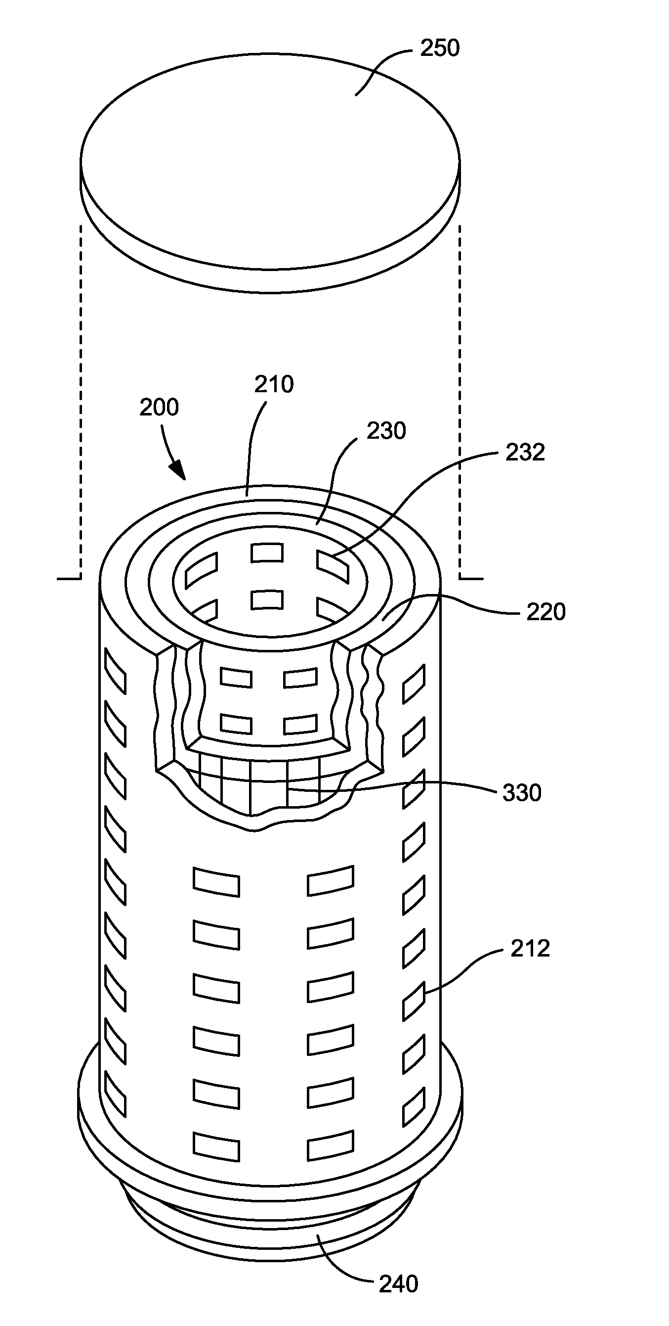
Vent Filter
[0055]In a first embodiment, a vent filter is employed. In a first embodiment, the filter is used as a vent filter.
[0056]FIG. 3 shows a container having such a vent. Typically, the container 201 is constructed from rigid materials, such as stainless steel and rigid plastic. In other embodiments, the container may be a flexible plastic material. To allow gasses to pass between the inside of the container 201 and the outside environment, typically a vent filter 200 is used. In the embodiment shown in FIG. 3, the filter element 200 is located at the top surface of the container 201, so that it is separated from the material contained within the container 201.
[0057]Vent filtration systems are used not only for bioreactors, but also for growth media, buffer solution, WFI (Water For Injection) preparation systems and filling applications. These vent filters are sterilized using a suitable technique, such as autoclave, Steam-In-Place, gas sterilization, such as using ETO (ethyle...
example 2
Particulate Filter
[0095]In another embodiment, a filtration system for particulates, such as cell debris from a bioreactor or crystals from wine, may employ the technology described above.
[0096]A filtration system for particulates such as cell debris from a bioreactor or crystals from wine is shown in FIG. 10. It consists of housing 702 containing one or more filters 704. The filter 704 is attached to the outlet 706 of the housing such that all filtrate reaching the outlet 706 does so by having first passed through the filter 704. The housing 702 also has an inlet 708 from a source of the fluid to be filtered. Downstream of the outlet 706 is a recirculation loop 710 which is connected via a first electronically actuated valve 714, such as a solenoid valve, to the outlet 706 and to the side of the housing 702 via a second electronically controlled valve 718. In the normal closed position, filtrate leaving the outlet 706 is passed downstream to the next location 718 such as a storage ...
PUM
 Abstract
Description
Claims
Application Information