Offshore hydro power station

Inactive Publication Date: 2013-01-10
BITERYAKOV ALEXEY
View PDF3 Cites 6 Cited by
  • Summary
  • Abstract
  • Description
  • Claims
  • Application Information

AI Technical Summary

Benefits of technology

The invention aims to improve the efficiency of wave power generation and reduce the cost of produced power. It offers the advantages of not requiring large structures above the water surface, not using compressed air or gas, adding more tank capacity easily, easy deconfiguration, and no need for technical problem removal or maintenance.

Problems solved by technology

Existing technologies face serious challenges harming the cost-effectiveness.
All this requires special engineering solutions to harness wave energy, leads to higher costs of the projects and badly affects the competitiveness of wave power generation.
This requires additional energy input and furthermore leaves residue of discharge gas in the sea, which could be potentially harmful to marine environment.
None of the above references disclose the use of suction pumps at the surface of a body of water controlled by a buoy at the surface to remove water from their underwater chambers.
Also, none of the references disclose the ease of assembly and disassembly of their apparatus that permits both expansion or reduction of their facilities.

Method used


Image

  • Offshore hydro power station
  • Offshore hydro power station
  • Offshore hydro power station

Examples


Embodiment Construction

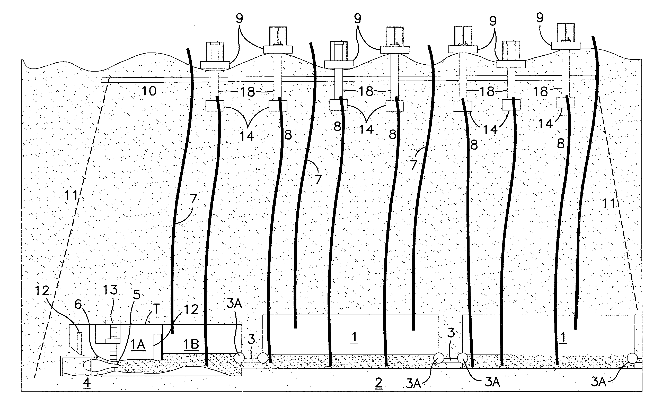
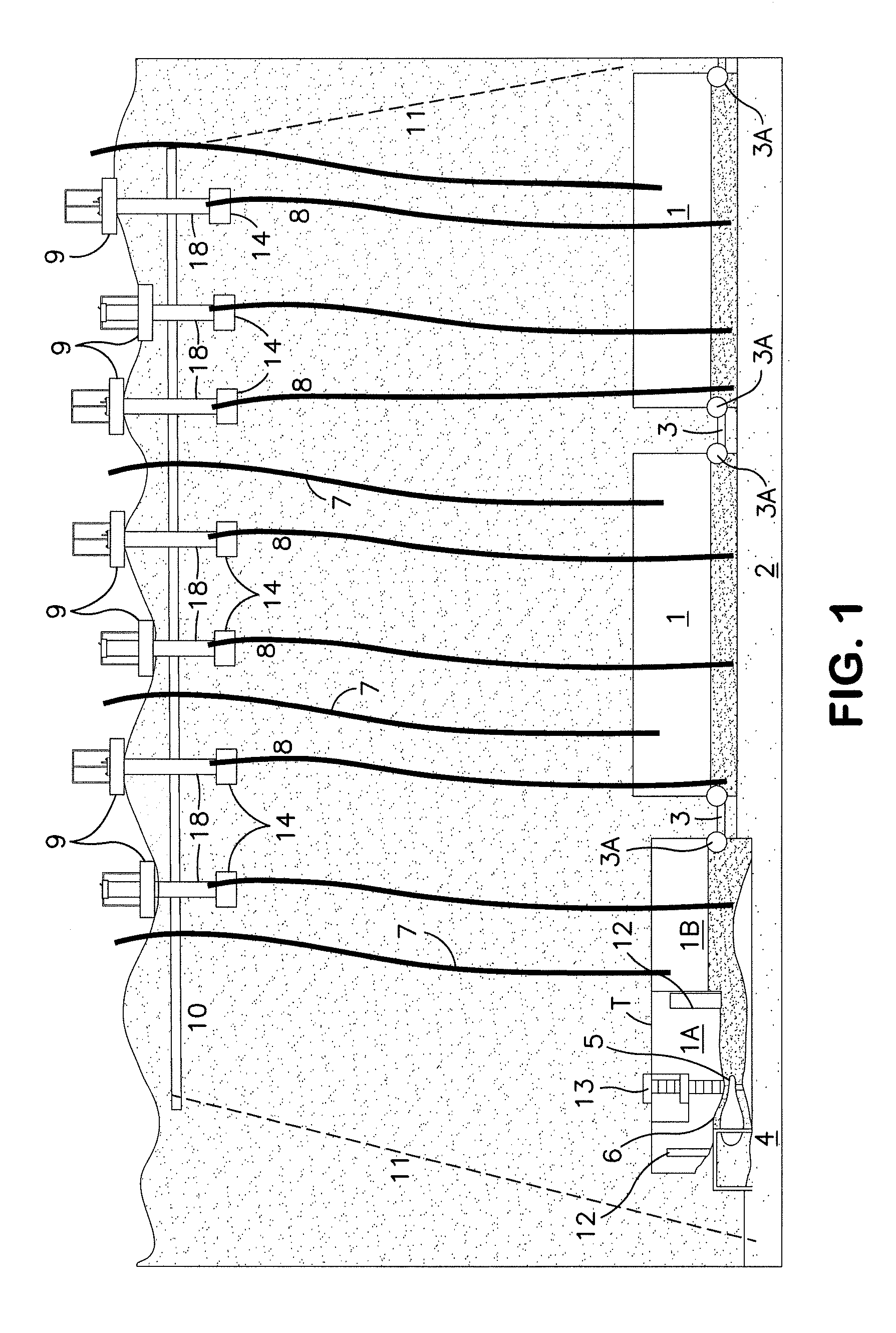
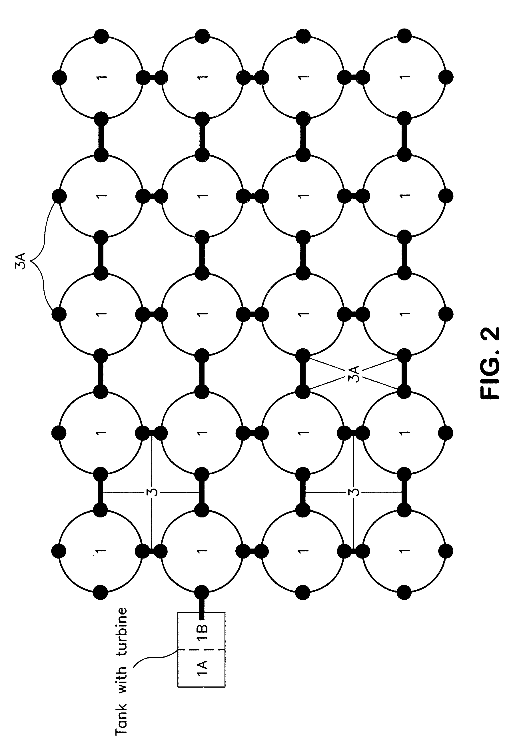
[0032]FIG. 1 shows a first embodiment which uses suction pumps to evacuate the water from underwater tanks 1, to generate electricity. The tanks can take a number of different shapes. The shapes shown are merely for illustration. Massive turbine tank T and water-accumulating tanks 1 are based on a large area of the seabed or another stable underwater structure 2. The tanks are connected to each other via connection pipes 3 so that the water coming into the first tank is distributed among all interconnected tanks. At any given time the water level in each tank is virtually the same, due to the interconnection of the tanks via pipes 3. Stopcocks 3A are positioned at the entrance and exit points of each tank to seal the tanks if needed.

[0033]As shown in FIG. 1, the first tank T is divided into two areas 1A and 1B. The area 1A houses the turbine 5 and generator 6 and has a system of doors and ladders 13 that allow human access into the turbine / generator area 1A. Area 1A also has a pair ...


PUM

PropertyMeasurementUnit
Pressureaaaaaaaaaa
Poweraaaaaaaaaa
Areaaaaaaaaaaa

Abstract

A system and a method of electric power generation utilizing sea wave energy is disclosed. The invention consists of an underwater system where seawater flows through an underwater turbine which generates electric power. The waste water that passes through the turbine then flows into underwater tanks on the seabed. According to the invention, simultaneously, water is pumped out of the underwater tanks to the surface by mechanical devices located at the surface utilizing wave motion.

Description

BACKGROUND OF THE INVENTION[0001]The present invention relates to the field of renewable energy, specifically to a method and system that produces electric power utilizing sea energy.DESCRIPTION OF THE PRIOR ART[0002]There has been much research and practical attempts to utilize marine energy resources. Wave power devices are generally categorized by the method used to capture the energy of the waves. The main types are: point absorbers or buoys; surface following devices or attenuators oriented parallel to the direction of wave propagation; terminators, oriented perpendicular to the direction of wave propagation; oscillating water columns; and overtopping devices.[0003]Existing technologies face serious challenges harming the cost-effectiveness. Among the challenges are included the following. The wave powered device has to efficiently convert wave motion into electricity. Generally speaking, wave power is available at low speed and high force, and the motion of forces is not in a ...

Claims


Application Information

Patent Timeline
IPC IPC(8): F03B13/20H02K15/00
CPCF03B13/10F03B13/1815F03B13/1875Y10T29/49009F05B2240/40Y02E10/38Y02E10/22F05B2230/60Y02E10/20Y02E10/30Y02P70/50
Inventor BITERYAKOV, ALEXEY
Owner BITERYAKOV ALEXEY
Why Eureka
Try Eureka