
Hybrid energy system

a hybrid energy system and energy technology, applied in the energy industry, greenhouse gas reduction, sustainable buildings, etc., can solve the problems of waste of resources, inefficiency of third and even forth systems, and wind turbine farms that are not designed to allow them

Active Publication Date: 2013-01-10
GILLETT CARLA R
View PDF13 Cites 98 Cited by
  • Summary
  • Abstract
  • Description
  • Claims
  • Application Information

AI Technical Summary

Benefits of technology

This patent describes a system that uses multiple methods to generate energy on a single site. The system includes a kinetic energy turbine that can be placed on buildings, bridges, and other structures. The system can also use other energy producing methods like piezoelectric valves and solar power panels. A controller manages the system and communicates with utility company headquarters. The system can generate and store electrical power for use by the business or for transmission to the grid. The technical effect of this system is to provide more diversified and efficient energy production on a single site.

Problems solved by technology

Wind turbine farm are not designed to allow a second, a third and even a forth system which is inefficient, and also waste resources.

Method used


Image

  • Hybrid energy system
  • Hybrid energy system
  • Hybrid energy system

Examples


Embodiment Construction

[0026]Hereinafter, a hybrid energy system will be described in details with reference to the drawings and the identical parts in the drawings are assigned the same reference numerals.

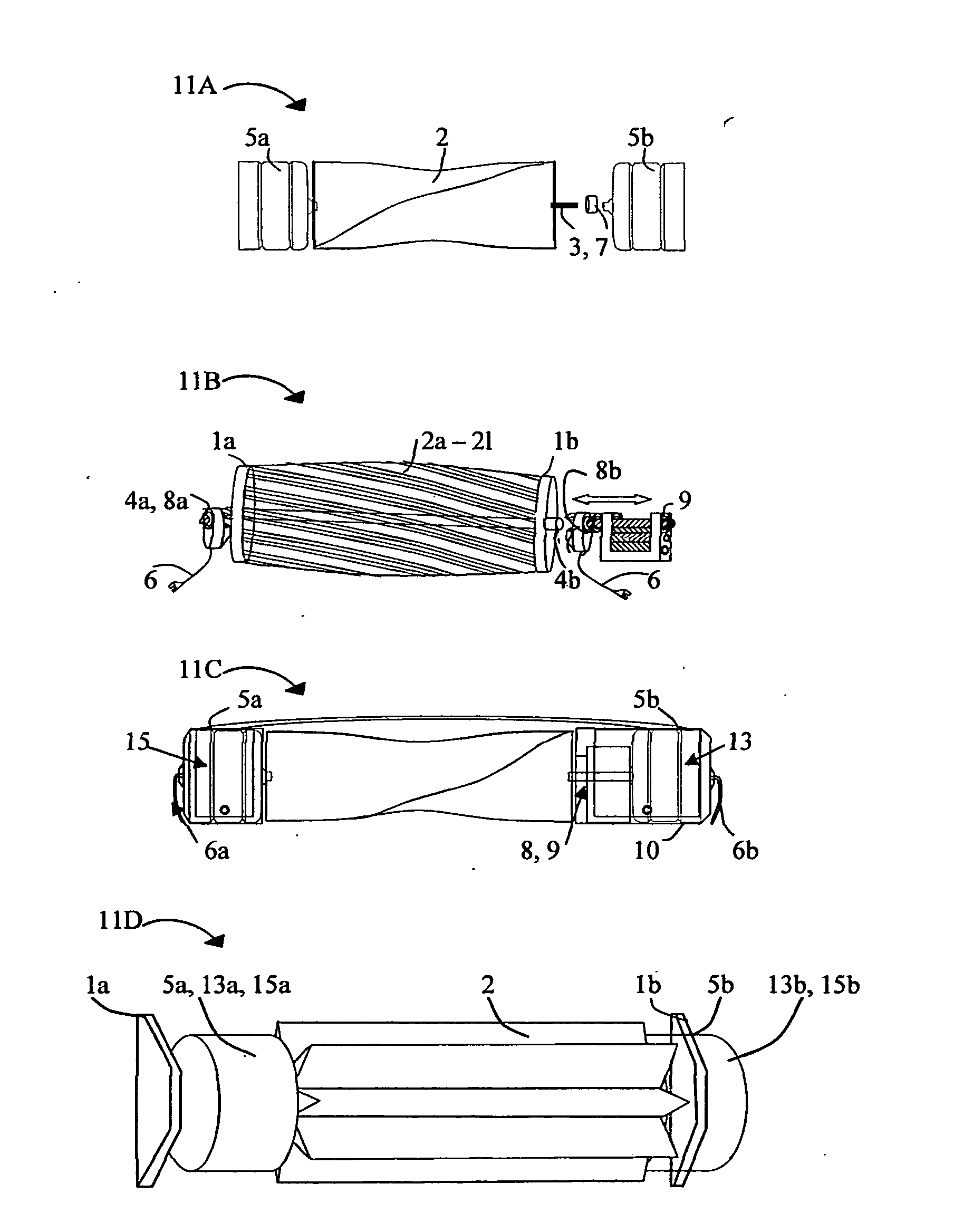
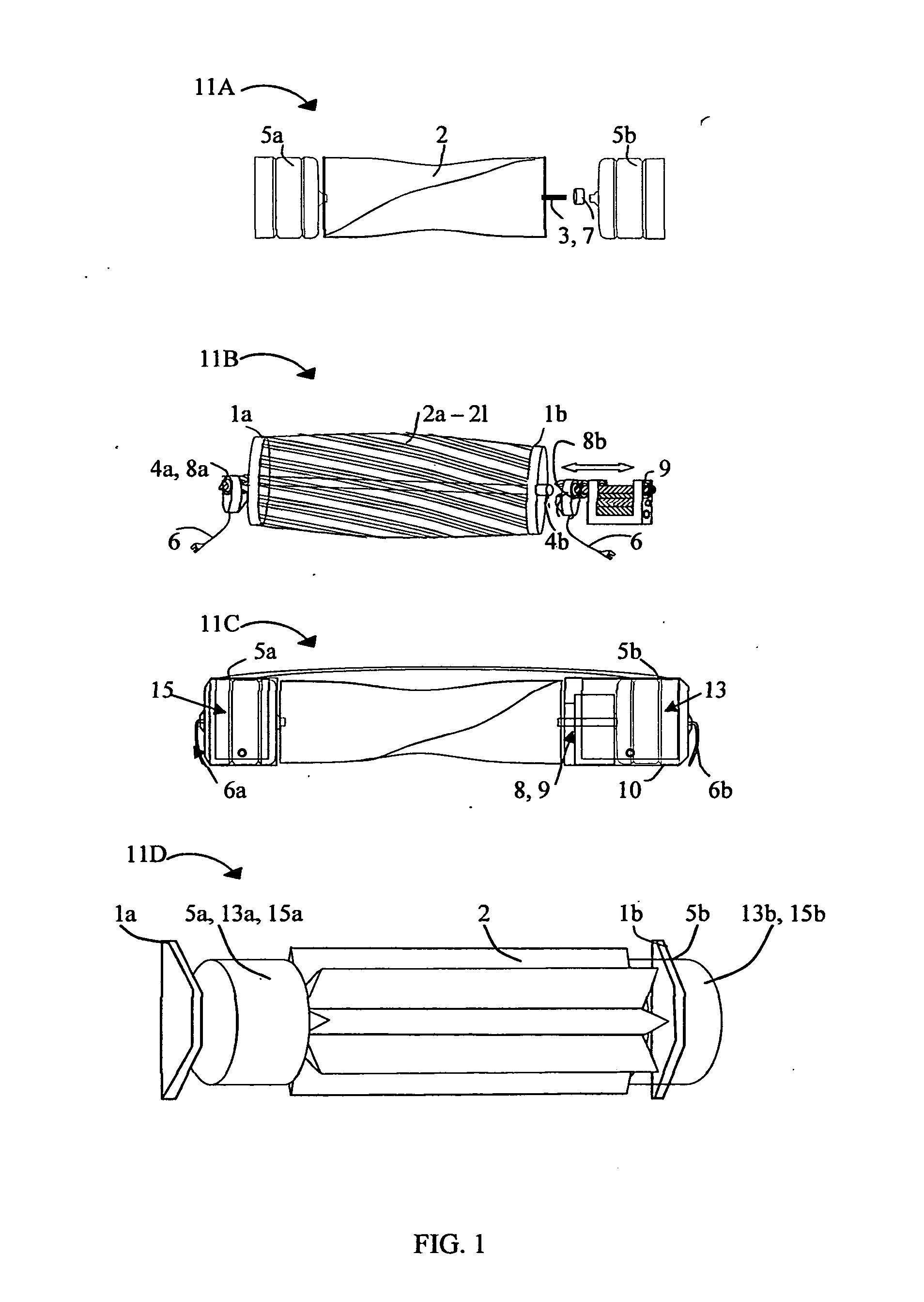
[0027]Referring now in greater detail in FIG. 1, a hybrid energy system illustrates various configurations for portable kinetic energy turbines 11A-11D and various methods include a kinetic energy turbine 11 supporting armature 1, frame support 2, blade type 3, a shaft 4 or two rods 4a, 4b, a generator or an alternator 5 A / C or D / C, electrical wiring 6, manual coupling 7, or electromagnetic coupling, electromagnetic coupling 8 which acts as a break, a gear box 9 which are contained within a nacelle 10, an encasement 15 with a hinged door with lock. Support armature 1 can mean a can, a rim, cable, brackets, and robotic arms.

[0028]FIG. 11A illustrates a configuration of a kinetic energy turbine comprising one generator 5a. The turbine rod 3 may or may not be manually coupled 7 with a second generator 5b. ...


PUM


Abstract

A hybrid energy system comprised of methods that work in conjunction with multiple kinetic energy turbine types, valves, solar power panels, piezoelectric devices and also element force. Hybrid energy powers electrical devices on site and extra power is also consigned off site. A network control system shunts surplus energy to the utility grid via above ground and underground cable. An on site power system charges a parked vehicle battery. A utility service vehicle is employed to deliver charged battery banks to on and off grid customers. A hybrid energy system integrates on rooftops, skyscrapers, bridges, tunnels, and aqueducts, as well as infrastructure on and off shore. A hybrid energy system integrates in various vehicle types and the power is managed accordingly by the vehicle control system.

Description

STATEMENT REGARDING FEDERALLY SPONSORED RESEARCH & DEVELOPMENT[0001]Non ApplicableTHE NAMES OF PARTIES TO A JOINT RESEARCH AGREEMENT[0002]Non ApplicableBACKGROUND OF THE INVENTION[0003]1. Field of the Invention[0004]This application relates to a hybrid energy system comprising collaborating kinetic energy turbine systems, turbine valves and pipes, solar power and piezoelectric devices which generate substantially more electricity at the same site, and also network controllers manage the electricity power on site and off site accordingly.[0005]2. Description of the Related Art[0006]As related art discloses, it is generally well known that there are wind turbines, hydroelectric turbines, piezoelectric systems and solar energy systems that are placed individually at a setting to generate electricity power. For example, related art discusses a giant wind turbine which requires about thirty acres and does not include a secondary power generating system on the same site. Wind turbine farm...

Claims


Application Information

Patent Timeline
Patent Type & Authority Applications(United States)
IPC IPC(8): H02J3/38
CPCH02J3/30H02J3/382Y02E60/16Y02E70/30Y02E10/763H02J3/386Y02E10/563Y02E10/566H02J3/383Y02B10/30H02J2300/40H02J2310/40H02J2310/44H02J2310/42H02J2300/28H02J2300/20H02J2300/24H02J3/381Y02B10/10Y02E10/56Y02E10/76Y02P80/10Y02P80/20Y02B10/70
Inventor GILLETT, CARLA R.
Owner GILLETT CARLA R
Learn More