Transformer

a technology of transformer and transformer, applied in transformers, power conversion systems, electrical equipment, etc., can solve the problems of mechanical complexity of tap changers, the load of electric motors driving pumps may vary over time, and damage to pump motors,

Inactive Publication Date: 2013-01-10
VETCO GRAY SCANDINAVIA
View PDF7 Cites 16 Cited by
  • Summary
  • Abstract
  • Description
  • Claims
  • Application Information

AI Technical Summary

Benefits of technology

[0027]The polyphase transformer may be arranged so that, wherein the legs, the yokes and the windings are enclosed by ...

Problems solved by technology

When power is supplied over cables of such length different problems may arise such as, e.g., charging of the cable feeding electricity to the pump.
The charging of the cable may give rise to an over-voltage at the pump motor, which ultimately may damage the pump motor, connection system, cable and/or topside electrical equipment.
Furthermore, during operation of a pump connected to the power supply ...

Method used


Image

  • Transformer
  • Transformer
  • Transformer

Examples


first embodiment

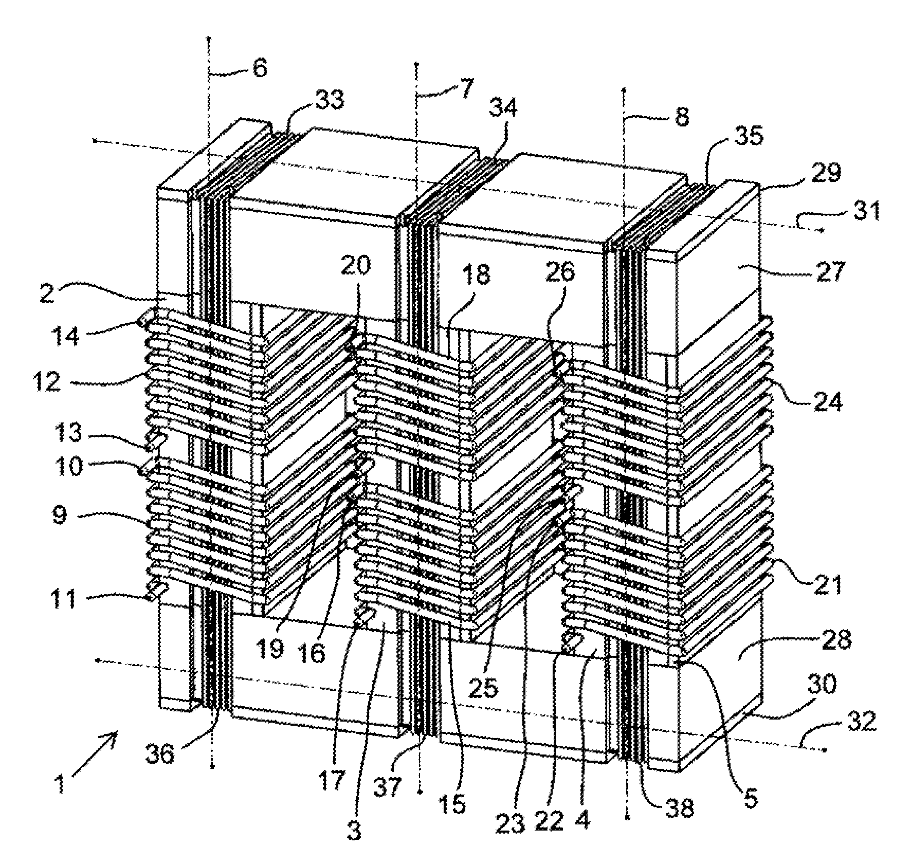
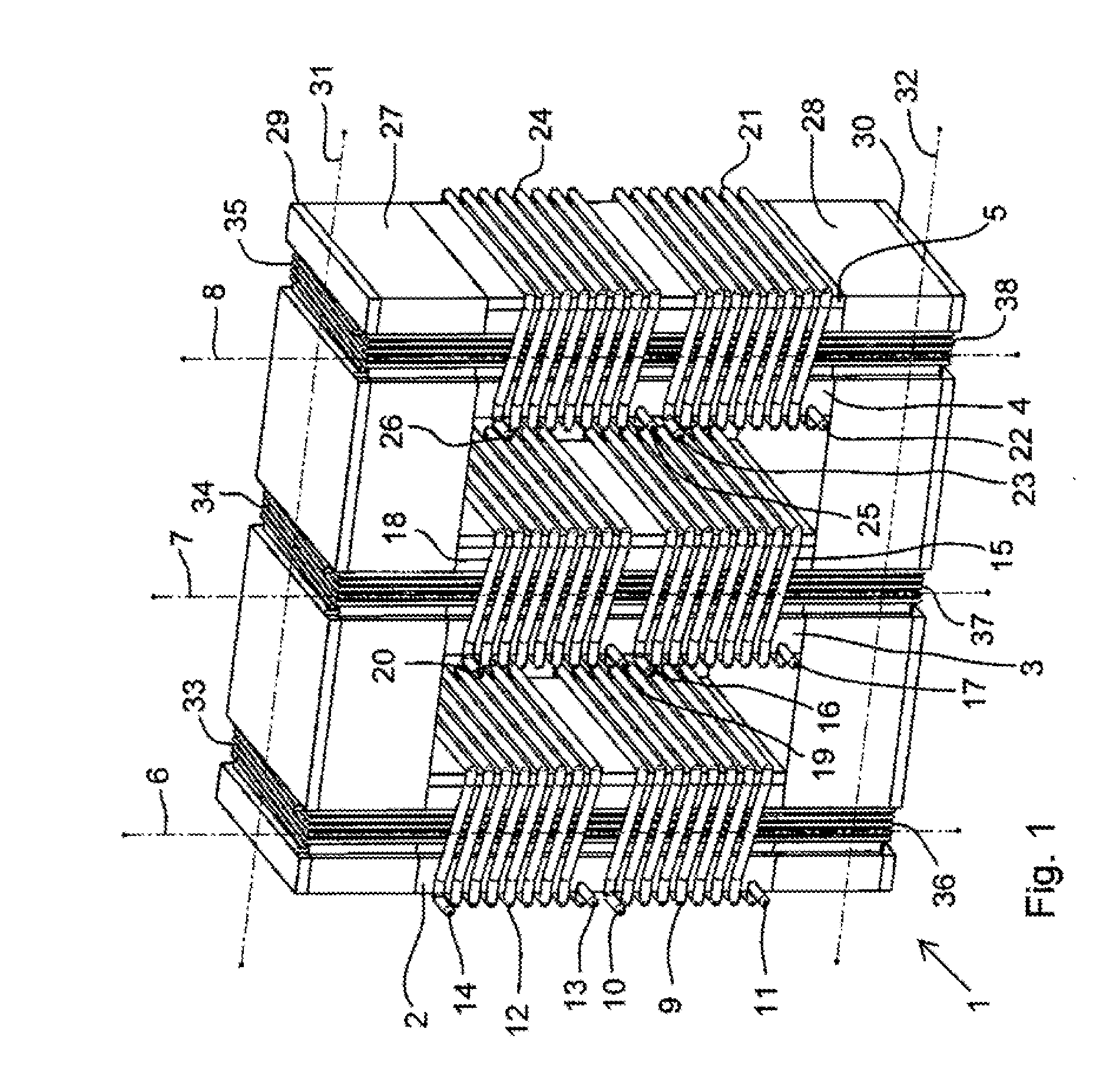
[0039]FIG. 1 shows a transformer 1 according to the present invention. The transformer 1 comprises a first leg 2, a second leg 3, and a third leg 4. Each one of the legs 2-4, comprises a large number of stacked plates of a magnetic material such as magnetic steel. One of the plates 5 is indicated in the third leg 4. The first leg 2 has a first length axis 6. The second leg 3 has a second length axis 7. The third leg 4 has a third length axis 8. The length axes 6-8 of the legs 2-4 are parallel to each other. A first primary winding 9 having a first tap 10 and a second tap 11 is arranged on the first leg 2. A first secondary winding 12 having a first tap 13 and a second tap 14 is arranged on the first leg 2. The winding axis of the first primary winding 9 is parallel to the winding axis of the first secondary winding 12 and parallel to the length axis 6 of the first leg. A second primary winding 15, with a first tap 16 and a second tap 17, and a second secondary winding 18, with a fir...

third embodiment

[0044]FIG. 4 shows a transformer 1 according to the present invention. The transformer 1 according to FIG. 4 differs from the embodiments in FIGS. 1 and 3 in that the control windings 48, 49, are orthogonal to the control windings in the embodiments of FIGS. 1 and 3 while still being arranged to produce a control magnetic field that is orthogonal to the primary magnetic fields induced by the primary windings 9, 15, 21. A first control winding 48 is wound around the upper yoke 27 and a second control winding 49 is wound around the lower yoke 28. In order to make it possible to wind the control windings 48, 49, as shown in FIG. 4 the yokes 27, 28, are preferably provided with recesses or grooves which form openings 50 between the legs 2-4 and the yokes 27, 28, on the assembled transformer 1. The openings will result in a higher resistance for the magnetic field which leads to losses and a decrease in the overall efficiency of the transformer 1.

fourth embodiment

[0045]FIG. 5 shows a transformer 1 according to the present invention in which the legs 51-53 are tubular. The legs 51-53 are circularly symmetrical around their length axes 6-8. The upper yoke 54 and the lower yoke 55 have through going holes 57, 58 (see also FIG. 6), corresponding to the holes of the legs 51-53. The first primary winding 56, and the first secondary winding 59 are wound through the hole of the first leg 51 and the corresponding holes 57, 58 of the yokes 54, 55. A second primary winding 60 and a second secondary winding 61 are wound in the corresponding way on the second leg 52, and a third primary winding 62 and a third secondary winding 63 are wound in the corresponding way on the third leg 53. The primary windings 56, 60, 62, are arranged to produce primary magnetic fields in the legs 51-53 orthogonal to the length axis 6, 7, 8, of the corresponding leg 51-53. Control windings (see FIG. 6) are wound to produce magnetic fields along the length axes of the legs 51-...


PUM


Abstract

A polyphase transformer (1) comprising at least a first leg (2, 51) and a second leg (3, 52) of a magnetic material is described. The transformer comprises a single core with legs (2-4, 51-53) and yokes (27, 28, 54, 55). A primary winding (9, 15, 21, 56, 60, 62) is arranged on each one of the legs (2-4, 51-53) arranged to produce primary magnetic fields in the legs (2-4, 51-53), a secondary winding (12, 18, 24, 59, 61, 63) is arranged on each one of the legs (2-4, 51-53). The winding axis of the primary winding (9, 15, 21, 56, 60, 62) and the winding axis of the secondary winding (12, 18, 24, 59, 61, 63) are essentially parallel to each other on each one of the legs (2-4, 51-53). The transformer (1) also comprises at least one control winding (33-35, 45-47, 48, 49, 73-75) arranged to produce magnetic fields in each one of the legs (2-4, 51-53) being essentially orthogonal to the primary magnetic fields in the legs (2-4, 51-53).

Description

TECHNICAL FIELD[0001]The present invention relates to a transformer and to an electric power distribution system comprising such a transformer. Primarily, but not limited to, the present invention relates to a high voltage transformer for an electric power distribution system in the form of an offshore system for electric power transmission from a power supply to a consumer means over a power transmission line comprising an offshore cable section.BACKGROUND OF THE INVENTION[0002]Offshore systems may be used to pump oil and / or gas from wells below the sea floor. Such systems may include pumps driven by electric pump motors for the pumping of the oil and / or gas. Such pumps may be situated hundreds of kilometres from the shoreline and may be supplied with electric power from a power supply arranged onshore. When power is supplied over cables of such length different problems may arise such as, e.g., charging of the cable feeding electricity to the pump. The charging of the cable may gi...

Claims


Application Information

Patent Timeline
IPC IPC(8): H02P13/12H01F30/12
CPCH01F29/14H02P13/12H01F2029/143H01F30/12
Inventor ROCKE, SVEND ERIKKNUTSEN, JAN-ERIK
Owner VETCO GRAY SCANDINAVIA
Why Eureka
Try Eureka