Charged-particle beam apparatus

a charge-particle and beam apparatus technology, applied in the direction of magnetic discharge control, instruments, heat measurement, etc., can solve the problems of large amount of outside dust disadvantageously entering each interior, small optical aberration, and inability to prevent dust from entering completely, so as to prevent electric discharge

Active Publication Date: 2009-01-08
HITACHI HIGH TECH SCI CORP
View PDF15 Cites 4 Cited by
  • Summary
  • Abstract
  • Description
  • Claims
  • Application Information

AI Technical Summary

Benefits of technology

[0021]In the charged-particle beam apparatus according to the present invention, the electrostatic lens generates the electric field, and the magnetic field lens generates the magnetic field so as to superimpose the magnetic field on the electric field. This configuration effectively converges the charged-particle beam.
[0022]In the charged-particle beam apparatus according to the present invention, the gas supplying means for supplying the gas into the chamber and the cylindrical body of the lens-barrel is provided at the proximal end side with respect to the objective lens. This configuration prevents dust, no matter how small amount it is of, from being attached to the electrostatic lens serving as the objective lens. Therefore, this configuration prevents electric discharge occurring due to the small amount of dust even when a high voltage is applied to the electrostatic lens and effectively converges the charged-particle beam to be emitted to the sample.

Problems solved by technology

Consequently, when the sample transport opening is open, a large amount of outside dust disadvantageously enters each interior in addition to outside air.
With regard to these charged-particle beams, when a high voltage is applied to an electrostatic lens used as an objective lens, optical aberration becomes small.
However, the application of a higher voltage to the electrostatic lens causes the following problem.
However, it is impossible to prevent the dust from entering completely.
In addition, since dust is also attached to the sample, a small amount of dust always exists in the chamber.
Herein, the dust is attached to the objective lens, resulting in electric discharge.

Method used


Image

  • Charged-particle beam apparatus
  • Charged-particle beam apparatus
  • Charged-particle beam apparatus

Examples


first embodiment

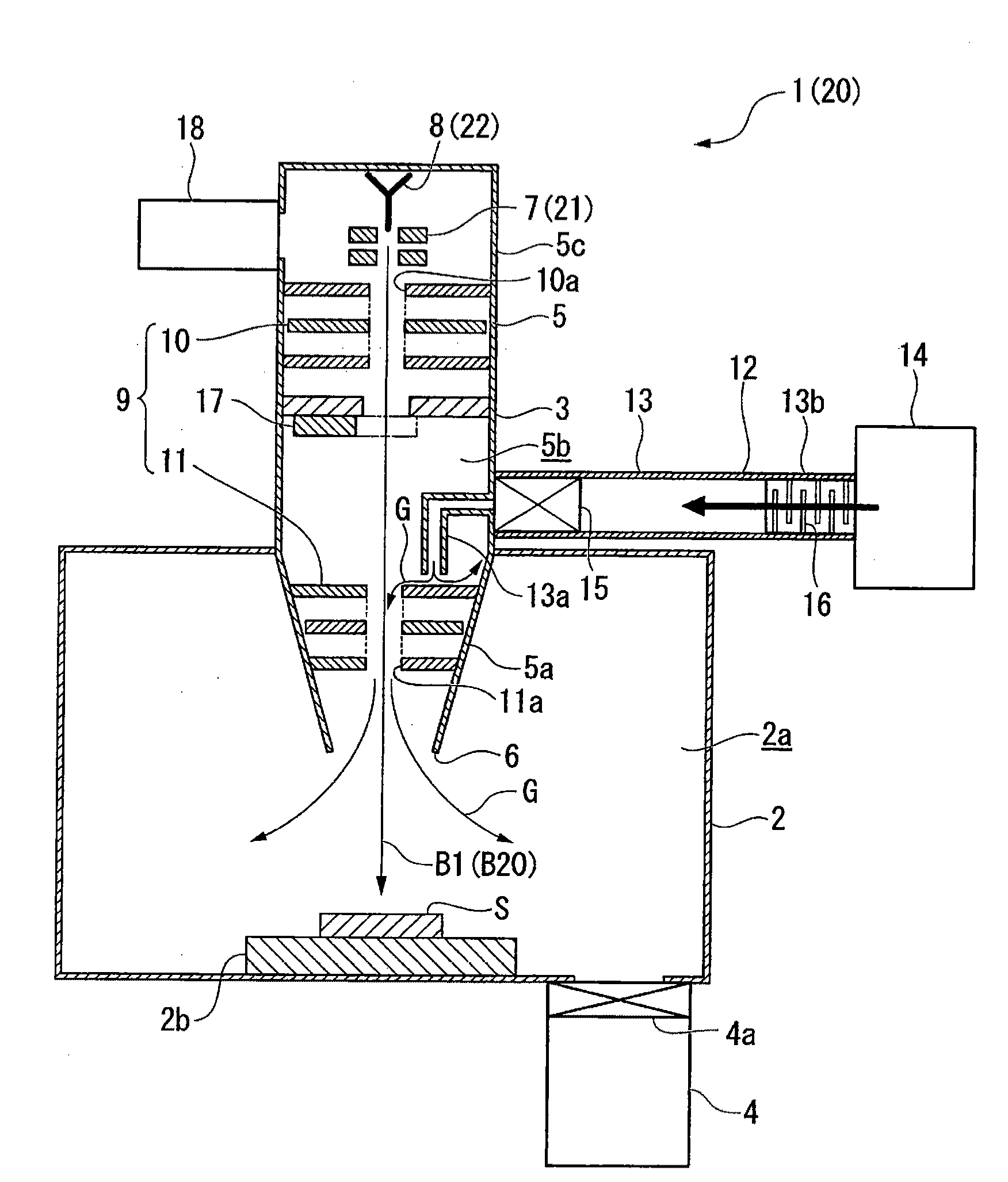
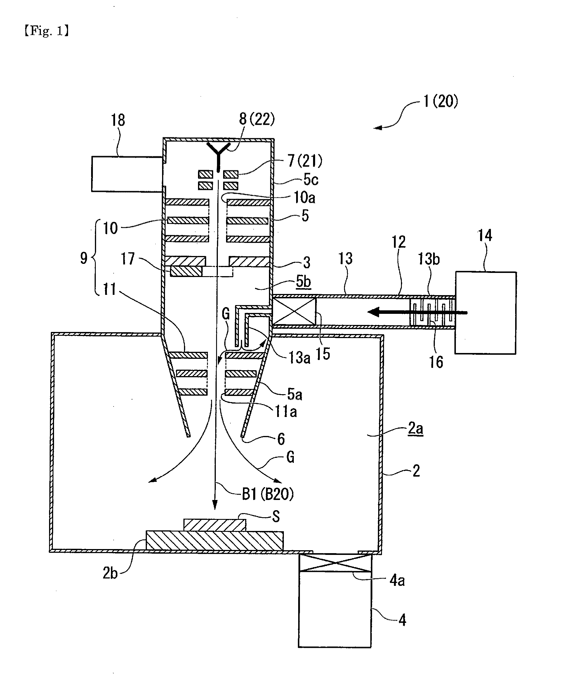
[0026]FIG. 1 shows a first embodiment according to the present invention. As shown in FIG. 1, a focused ion beam apparatus (FIB) 1 serving as a charged-particle beam apparatus emits an ion beam B1 serving as a charged-particle beam to a sample S to fabricate a surface of the sample S. For example, a wafer is placed in the apparatus as the sample S to prepare a sample for observation using a TEM (Transmission Electron Microscope). Moreover, a photomask in photolithography is used as the sample S in order to correct the photomask. Hereinafter, detailed description will be given of the focused ion beam apparatus 1 according to this embodiment.

[0027]As shown in FIG. 1, the focused ion beam apparatus 1 includes a chamber 2 having an interior 2a in which a sample stage 2b is disposed, and a lens-barrel 3 emitting the ion beam B1 to the sample S placed on the sample stage 2b. The chamber 2 is provided with an intra-chamber evacuating means 4 evacuating the interior 2a of the chamber 2 to s...

second embodiment

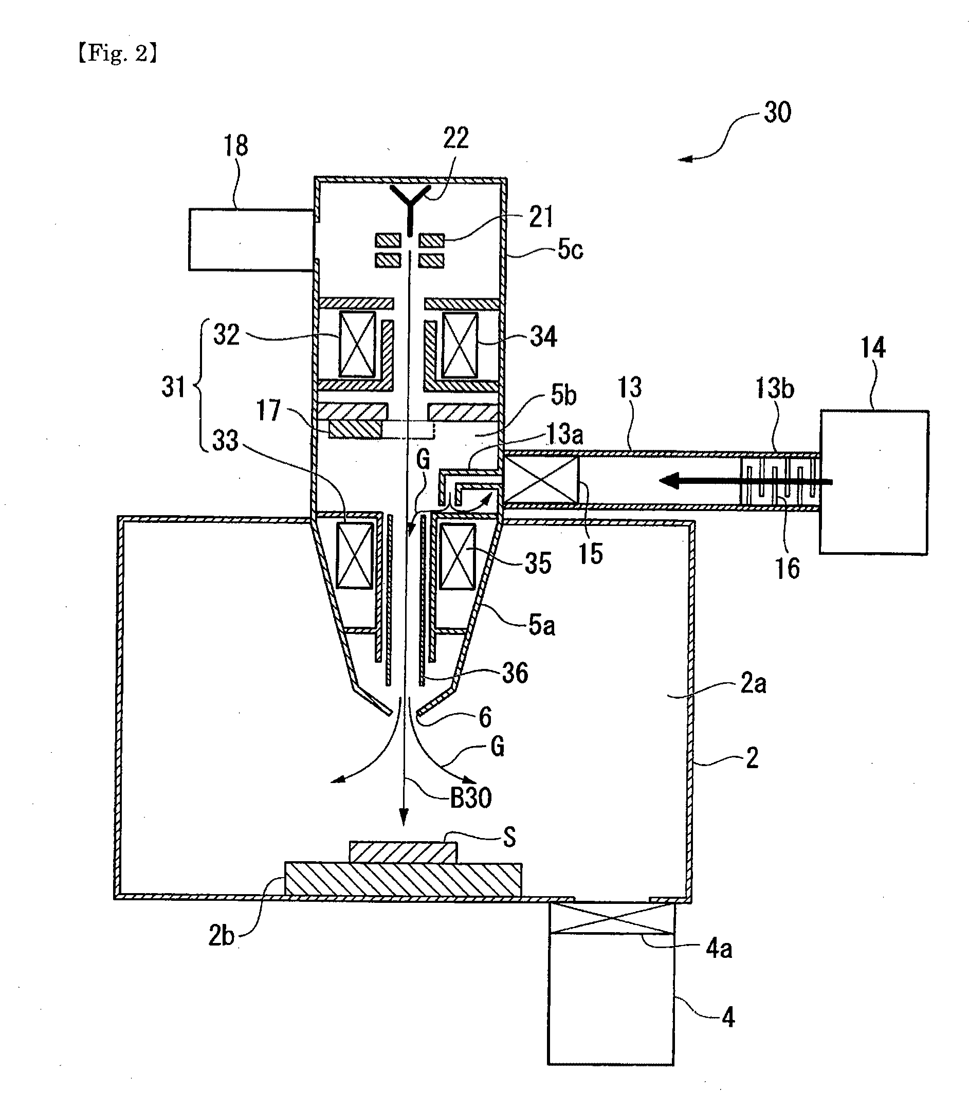
[0034]FIG. 2 shows a second embodiment according to the present invention. In this embodiment, members equal to those used in the foregoing embodiment are denoted by identical reference symbols; therefore, description thereof will not be given here.

[0035]As shown in FIG. 2, a scanning electron microscope (SEM) 30 serving as a charged-particle beam apparatus includes, as an optical system 31, a condenser lens 32 and an objective lens 33. The condenser lens 32 has a coil 34 functioning as a magnetic field lens. On the other hand, the objective lens 33 has a coil 35 functioning as a magnetic field lens, and an electrode 36 functioning as an electrostatic lens inserted into the coil 35. In the condenser lens 32, an electric current is fed to the coil 34 to generate a magnetic field. In the objective lens 33, on the other hand, a voltage is applied to the electrode 36 to generate an electric field and an electric current is fed to the coil 35 to generate a magnetic field so as to superim...


PUM

PropertyMeasurementUnit
temperatureaaaaaaaaaa
electric fieldaaaaaaaaaa
vacuumaaaaaaaaaa

Abstract

Provided is a charged-particle beam apparatus capable of preventing a small amount of dust from being attached to an electrostatic lens serving as an objective lens to apply a high voltage to the electrostatic lens.
The charged-particle beam apparatus 1 includes a chamber 2 which has an interior 2a evacuated by an intra-chamber evacuating means 4, and a lens-barrel 3 which emits a charged-particle beam B1 onto a sample S put in the interior 2a of the chamber 2. The lens-barrel 3 includes a cylindrical body 5 which includes an emission outlet 6 for emission of the charged-particle beam B1, a charged-particle supply part 7 which is housed at a side of a proximal end 5b in an interior 5a of the cylindrical body 5 and releases the charged-particle beam B1, and an objective lens 11 which is housed at a side of a distal end 5b in the interior 5b of the cylindrical body 5 and has an electrostatic lens for generating an electric field and converging the charged-particle beam B1 released from the charged-particle supply part 7. The cylindrical body 5 of the lens-barrel 3 is provided with a gas supplying means 12 capable of supplying a gas G to the interior 5b of the cylindrical body 5, and the gas supplying means 12 is provided at a side of a proximal end of the objective lens 11.

Description

RELATED APPLICATIONS[0001]This application is a continuation of PCT / JP2007 / 050190, filed on Jan. 11, 2007, which claims priority to Japanese Application No. JP2006-016159, filed on Jan. 25, 2006. The entire contents of these applications are incorporated herein by reference.TECHNICAL FIELD[0002]The present invention relates to a charged-particle beam apparatus for emitting a charged-particle beam onto a sample to fabricate or observe the sample.BACKGROUND ART[0003]Conventionally, there has been proposed a charged-particle beam apparatus for emitting a charged-particle beam onto a sample in a vacuum atmosphere to fabricate or observe a surface of the sample. FIG. 3 schematically shows a charged-particle beam apparatus 50 as described above. The charged-particle beam apparatus 50 includes a chamber 51 in which a sample S is placed, and a lens-barrel 52 for directing a charged-particle beam B onto the sample S placed in the chamber 51. The lens-barrel 52 includes a charged-particle sup...

Claims


Application Information

Patent Timeline
Patent Type & Authority Applications(United States)
IPC IPC(8): G01N23/00H01J3/20H01J3/18
CPCH01J37/02H01J37/16H01J2237/31749H01J2237/022H01J2237/12H01J37/185
Inventor OGAWA, TAKASHIMUTO, HIROTO
Owner HITACHI HIGH TECH SCI CORP
Why Eureka
Try Eureka