Track bushing and method and apparatus for producing the same

Inactive Publication Date: 2006-07-06
KOMATSU LTD
View PDF19 Cites 0 Cited by
  • Summary
  • Abstract
  • Description
  • Claims
  • Application Information

AI Technical Summary

Benefits of technology

[0090] Preferably, the induction heater is a spiral coil for preventing an electric discharge phenomenon at the contact parts of adjacent track bushings or at the position of each partition jig disposed between adjacent track bushings, in cases where a plurality of track bushings are heated at the same time. Preferably, the supporting device is designed to be rotatable and vertically movable.
[0091] A fifth aspect of the present application resides in that in order to solve the problem of occurrence of quenching cracks which are likely to occur at the time of quenching if the outer circumferential surface of the track bushing is heated higher than the

Problems solved by technology

The carburization method ① produces a track bushing having good functionality as a pre-lubricated bushing because the end faces of the bushing are uniformly carburization hardened, but presents the problem that it takes a long time to carburize because the carburization-hardened case needs to be deepened in order to increase the wear resistance of the outer circumferential cylindrical surface, and use of a large amount of carburization gas leads to increased cost.
In addition, where a large-sized track bushing having a great wall thickness is produced by the carburization method ①, the depth of the hardened case must be great in view of strength and wear resistance, which results in a decrease in yield and high cost.
Further, since carburization heating of the inner and outer circumferential surfaces takes a long time, a grain boundary oxidation layer or imperfectly quenched layer of several tens of μm is formed in the inner and outer circumferential surfaces so that fatigue strength and impact resistance properties are likely to degrade.
The induction hardening method ② has been improved over the carburization method ① in terms of cost, but disadvantageously requires two quenching processes, i.e., quenching from the inner and outer circumferential surfaces, so that it cannot be regarded as a satisfactory thermal treatment having improved productivity and cost performance.
Additionally, in this induction hardening method, irregularities and omissions in quenching of the end faces of the pre-lubricated track bushing are unavoidable and therefore there arises a problem in ensuring the wear resistance of the end face serving as a dust seal face for preventing penetration of earth and sand into the inner circumference section of the bushing.
The method ③, in which the outer circumferential surface is cooled after preceding cooling of the inner circumferential surface, has the advantage that a track bushing excellent in wear resistance can be produced at very low cost by one quenching operation, but presents the drawback that if spray cooling is employed for cooling the inner circumferential surface of a cylindrical tube of small inside diameter, satisfactory cooling performance and uniformity cannot be ensured, because a surface to be cooled is usually positioned at a distance apart from the nozzle, the distance being about 10 times the bore diameter of the nozzle, in order to obtain an increased heat transfer coefficient and because the ability to

Method used


Image

  • Track bushing and method and apparatus for producing the same
  • Track bushing and method and apparatus for producing the same
  • Track bushing and method and apparatus for producing the same

Examples


example 1

Heating Test 1

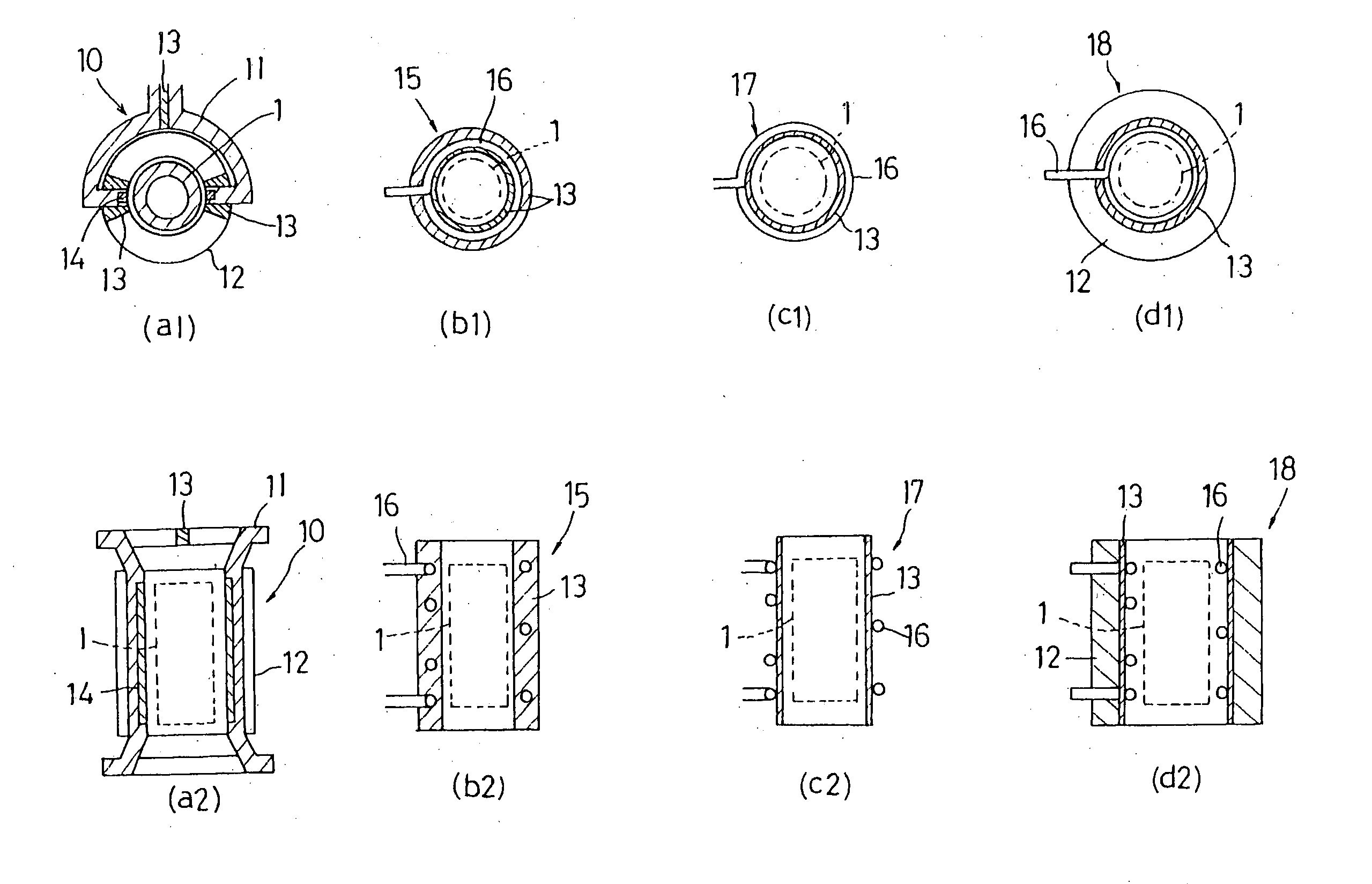
[0154] In this example, the saddle-shaped heating inductor 11 having ferrite iron 14 embedded in the inner circumferential surface thereof as shown in FIG. 9 was used as the heating inductor for induction heating. The outer circumferential surface cooling jacket 12 was disposed on the peripheral side of the saddle-shaped heating inductor 11 and the guide tube (water guide tube) 2 for cooling water was disposed in the bore of the heating inductor 11. The length of the embedded ferrite iron 14 was substantially equal to the length of the track bushing 1. The saddle-shaped heating inductor 11 was about 3 mm away from the outer circumferential surface of the track bushing 1. A high frequency heating power source of 6 kHz and 300 kW was used. In FIG. 9, reference numeral 13 designates an insulating material.

[0155] As shown in FIG. 10, the track bushing 1 was fixed at its upper and lower ends by means of the upper partition jig 7 and lower partition jig 8 for dividing the ...

example 2

Heating Test 2

[0158] In this example, induction heating was done, using the spiral coil 16 such as shown in FIG. 12 for the track bushing B in order to prevent the electric discharge phenomenon observed in Example 1. The basic design of the spiral coil 16 is as follows: A copper tube of φ 10 mm was wound such that the coil spacing was 10 to 25 mm, the inside diameter of the coil was about 15 mm larger than the outside diameter of the track bushing, and a ½ turn at each coil end was parallel with the associated end face of the track bushing. The same high frequency power source as in Example 1 was used to heat the track bushing B with an input power of 110 kW per bushing. The time required for heating the track bushing B to about 950° C. was about 12 seconds.

[0159] Where heating was carried out using partition jigs (see FIG. 10) made from SUS304, it was found that the electric discharge phenomenon at the contact parts of the partition jigs was not observed and the abnormal heating ...

example 3

Inner Circumferential Surface Cooling System and Observation of Cooling Condition

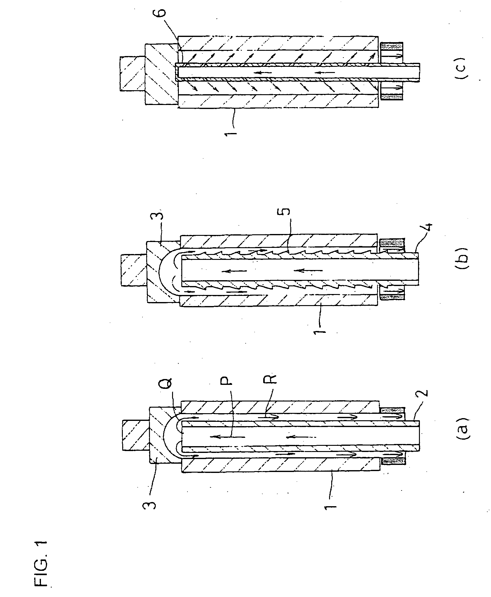
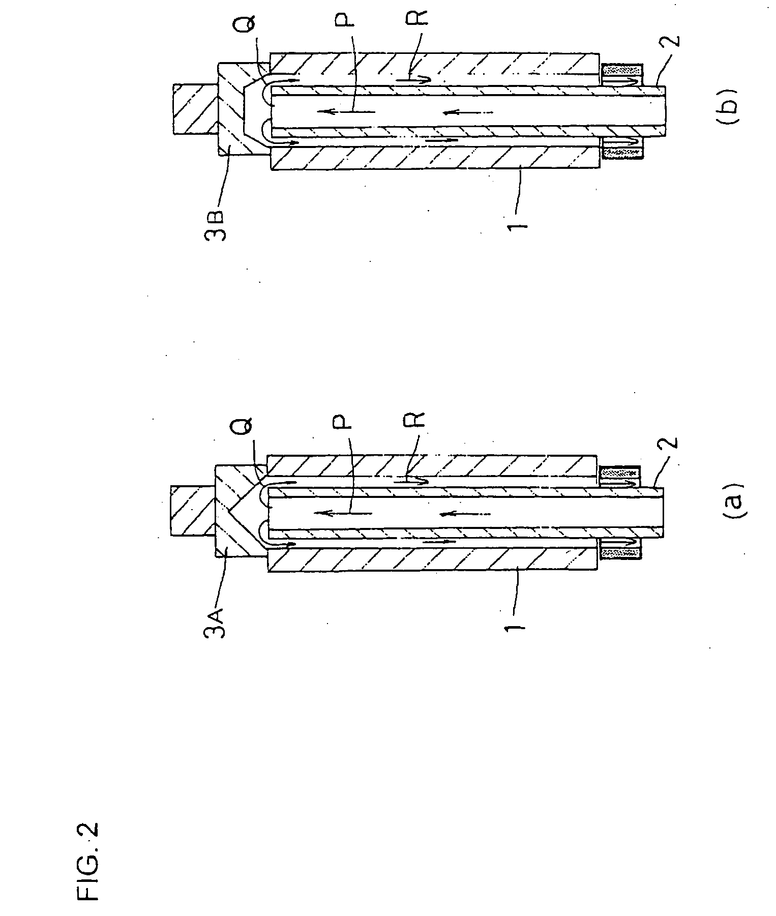
[0162] In Example 3, a flowing test by visual inspection was made in the following way: Water was used as the cooling medium for inner circumferential surface cooling and a transparent, cylindrical acrylic resin tube having the same inside diameter as that of the track bushing was used in place of the track bushing. More concretely, the outside diameter of the guide tube 2 for cooling water was varied so as to be 2, 4, 8, 10 and 20 mm smaller than the inside diameter of the track bushing (acrylic resin cylindrical tube) 1 as shown in FIG. 13. By use of the upper partition jig 7 including a spherical surface having a slightly smaller diameter than the inside diameter of the track bushing 1, cooling water was flowed downwardly from above the cylindrical axis of the track bushing into the space defined by the inner circumferential surface of the track bushing 1 and the outer circumferential surface of the...


PUM

PropertyMeasurementUnit
Fractionaaaaaaaaaa
Fractionaaaaaaaaaa
Fractionaaaaaaaaaa

Abstract

Quenched layers are formed without irregularities on the inner circumferential surface of a track bushing having a small inside diameter or on the inner circumferential surfaces of two or more track bushings which are subjected to quenching in an overlapped condition. To introduce a cooling medium for cooling the inner circumferential surface of the track bushing, a guide tube having an outside diameter smaller than the inside diameter of the track bushing is disposed on the side of the inner circumferential surface and the cooling medium introduced by the guide tube is diverted by a diverting member having a spherical or similar curved surface, such that the cooling medium is allowed to flow in a direction substantially parallel with an axial direction of the track bushing 1 within a space defined by the outer circumferential surface of the guide tube and the inner circumferential surface of the track bushing, thereby performing laminar flow cooling.

Description

TECHNICAL FIELD [0001] The invention relates to a track bushing for use in construction machines such as bulldozers, and a method and apparatus for producing the same. More particularly, the invention relates to a track bushing excellent in wear resistance and impact fatigue resistance, and a method and apparatus for producing such a track bushing at low cost, by use of a simpler means. BACKGROUND ART [0002] A known crawler belt 51 for use in a construction machine or the like comprises assemblage of parts such as shown in FIG. 23. Among them, a track bushing 52 is required to have wear-resistance at its inner and outer circumferential surfaces as well as high strength and toughness as a bushing, because it engages sprocket teeth for transmitting rotational movement from final reduction gears and functions to rotate the crawler belt 51. In a high speed running condition, there have been used pre-lubricated crawler belts containing a lubricant in a gap between a track pin 53 and the ...

Claims


Application Information

Patent Timeline
IPC IPC(8): C21D1/10E02F9/02B62D55/21C21D1/18C21D1/42C21D1/62C21D9/00C21D9/08C21D9/14
CPCC21D1/18C21D1/42C21D9/085B62D55/21C21D1/62C21D9/08C21D9/14C21D2221/10Y02P10/25C21D9/00
Inventor TAKAYAMA, TAKEMORIOKAYAMA, CHIGOOHISHI, MASAYUKITERAO, TAKEYO
Owner KOMATSU LTD
Why Eureka
Try Eureka