Photonic system and method for optical data transmission in medical imaging systems

a technology of optical data transmission and imaging system, applied in multiplex communication, instruments, healthcare informatics, etc., can solve the problems of increasing the weight and complexity of a given array, limiting the number of detection features in a given detector array, and limited scanning speed and resolution of these modalities with a given type of detection array

Inactive Publication Date: 2013-01-10
GENERAL ELECTRIC CO
View PDF1 Cites 21 Cited by
  • Summary
  • Abstract
  • Description
  • Claims
  • Application Information

AI Technical Summary

Benefits of technology

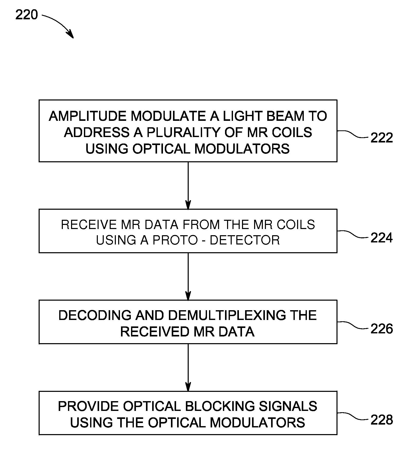
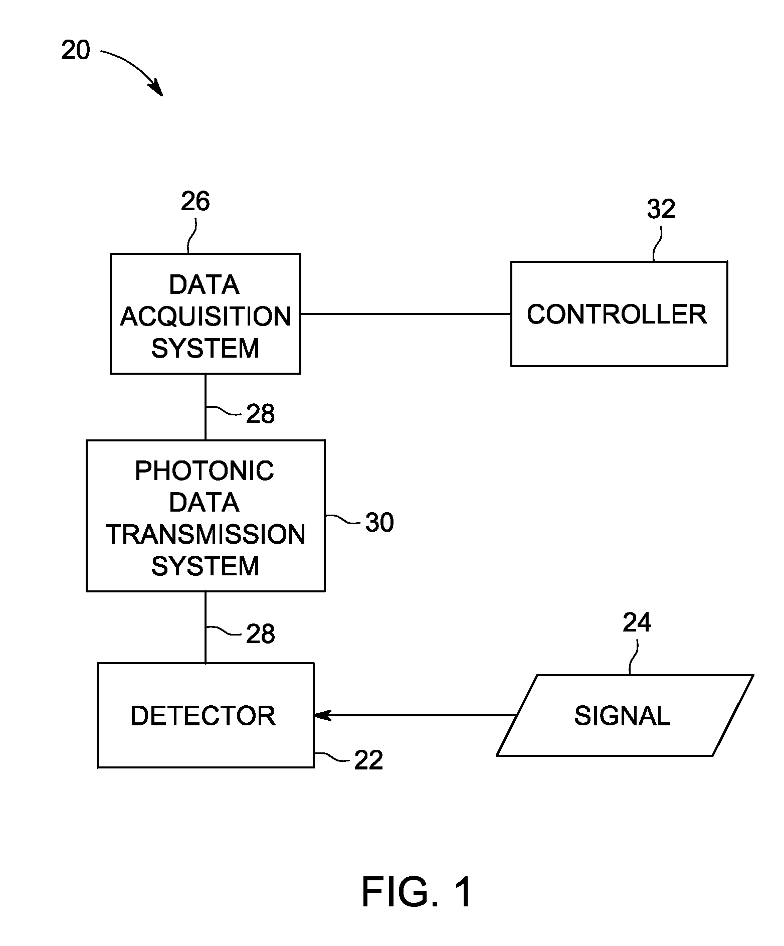
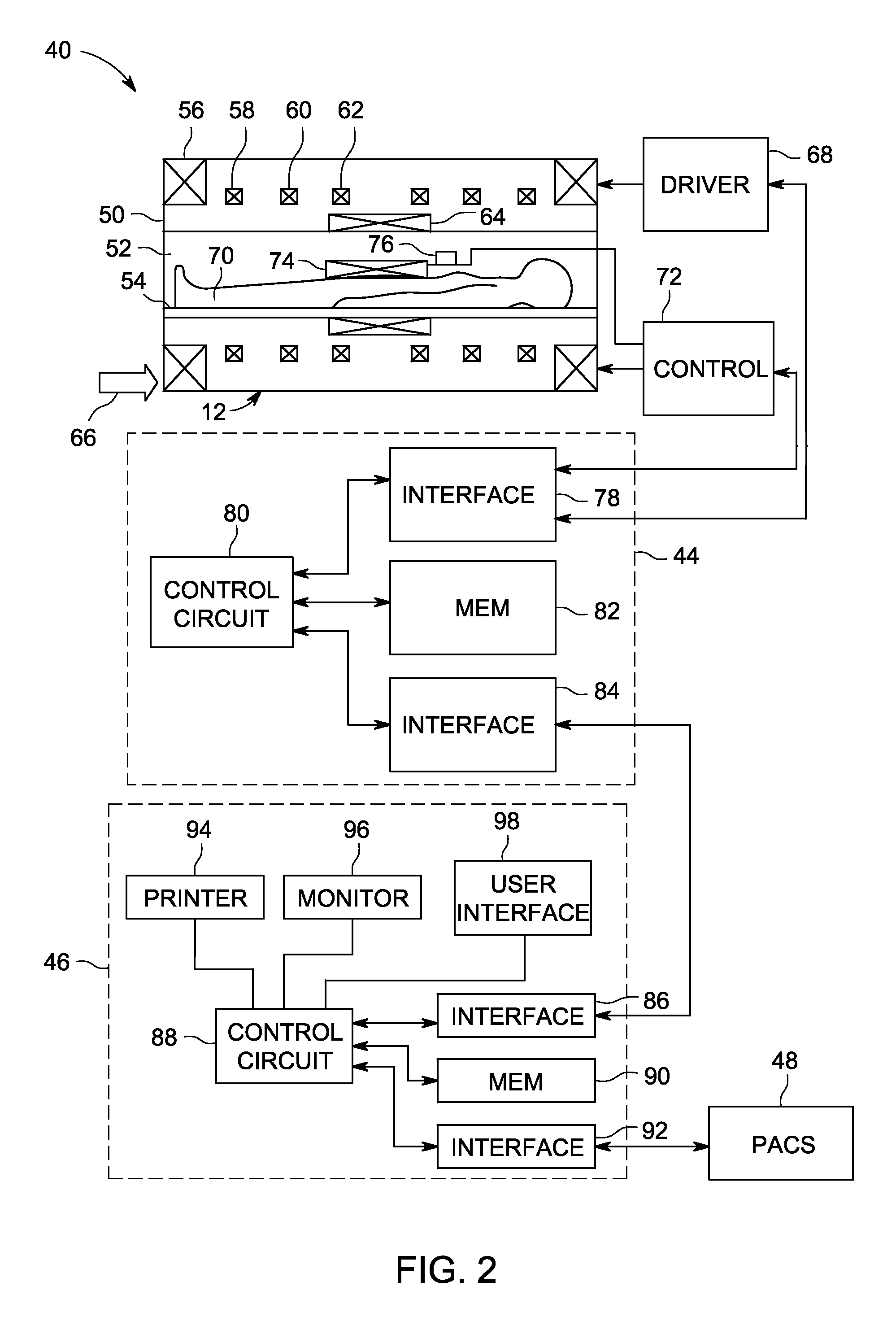
[0005]In accordance with other various embodiments, a photonic data transmission system for a Magnetic Resonance Imaging (MRI) system is provided. The photonic data transmission system includes a light source operable to produce a beam of light comprising one or more discrete optical wavelengths and one or more modulation frequencies, wherein the discrete optical wavelengths are amplitude modulated at different Radio-Frequency (RF) frequencies. The photonic data transmission system further includes a plurality of optical modulators configured to receive electrical signals representative of a set of medical data from a plurality of receive coils of the MRI system. Each optical modulator is operable to modulate a subset of photons corresponding to an optical wavelength within an encoded beam of light to encode the photons with the set of medical data from a corresponding receiver coil to produce encoded photons, wherein each modulator is selectable using a different optical wavelength and RF mixing frequency for the amplitude modulated beam of light. The photonic data transmission system also includes an optical waveguide interfacing the light source and the plurality of optical modulators with an opto-receiver configured to remove the encoded photons from the encoded beam of light. The photonic data transmission system further includes receiver opto-electronics configured to decode the encoded beam of light received by the opto-receiver and convert the decoded beam of light into the electrical signals representative of the set of medical data.

Problems solved by technology

Because the number of system channels available may be limited, the number of detection features in a given detector array is often limited.
As a result of the limited number of detection features, the scanning speed and the resolution of these modalities with a given type of detection array may be limited.
Additionally, each of the channels not only require extra electrical materials and power to amplify the signals produced by the detectors, but also increase the weight and complexity of a given array.
For example, MRI systems can include high-density multiple-coil MRI receiver arrays having increased cabling density, power consumption and protective device overhead.
In particular, the complexity of the receiver-array cabling and protective elements has increased significantly with the use of 64 and 128 channel systems, resulting in a higher likelihood of signal-to-noise (SNR) degradation, preamp instability, and cable / balun heating from the RF transmit field.

Method used


Image

  • Photonic system and method for optical data transmission in medical imaging systems
  • Photonic system and method for optical data transmission in medical imaging systems
  • Photonic system and method for optical data transmission in medical imaging systems

Examples


Embodiment Construction

[0015]The foregoing summary, as well as the following detailed description of certain embodiments, will be better understood when read in conjunction with the appended drawings. To the extent that the figures illustrate diagrams of the functional blocks of various embodiments, the functional blocks are not necessarily indicative of the division between hardware. Thus, for example, one or more of the functional blocks may be implemented in a single piece of hardware or multiple pieces of hardware. It should be understood that the various embodiments are not limited to the arrangements and instrumentality shown in the drawings. Additionally, the system blocks in the various figures or the steps of the methods may be rearranged or reconfigured.

[0016]As used herein, an element or step recited in the singular and proceeded with the word “a” or “an” should be understood as not excluding plural of said elements or steps, unless such exclusion is explicitly stated. Furthermore, references t...


PUM


Abstract

A photonic system and method for optical data transmission in medical imaging system are provided. One photonic system includes a plurality of optical modulators having different optical resonance wavelengths and configured to receive electrical signals representative of a set of data from a medical imaging device. The photonic system also includes an optical waveguide interfacing with the plurality of optical modulators and configured to transmit an amplitude modulated beam of light at different frequencies to selectively modulate the plurality of optical modulators to transmit an encoded beam of light. The photonic system further includes receiver opto-electronics in communication with the optical waveguide configured to decode the encoded beam of light and convert the decoded beam of light into the electrical signals representative of the set of data.

Description

BACKGROUND[0001]The subject matter disclosed herein relates generally to data transmission in imaging and communication systems, and more specifically, to the communication of control signals and data via photonics within medical imaging systems, such as in Magnetic Resonance Imaging (MRI) systems.[0002]In different imaging modalities, the quality, resolution, and / or speed of a resulting image is dependent on the number of detection elements (e.g., photodiodes, transducers, or coils) in respective detector arrays. As these imaging modalities add detection features, a system channel that electrically couples each detection feature to transmit and / or receive circuitry is needed. Because the number of system channels available may be limited, the number of detection features in a given detector array is often limited. As a result of the limited number of detection features, the scanning speed and the resolution of these modalities with a given type of detection array may be limited. As...

Claims


Application Information

Patent Timeline
Patent Type & Authority Applications(United States)
IPC IPC(8): H04J14/00G16H30/20G16H40/67
CPCG06F19/321H04B10/801A61B8/56A61B6/566H04J14/0298G16H30/20G16H40/67
Inventor HARDY, CHRISTOPHER JUDSONMANIPATRUNI, SASIKANTH
Owner GENERAL ELECTRIC CO
Why Eureka
Try Eureka