In situ bioremediation of contaminated groundwater using electron acceptor salts

a technology of electron acceptor salt and groundwater, which is applied in the direction of biological water/sewage treatment, water treatment compounds, water treatment parameter control, etc., can solve the problems of btex compounds being susceptible to anaerobic biodegradation, low solubility of dissolved oxygen in water, and low dissolved oxygen solubility in water

Active Publication Date: 2013-01-17
CHEVROU USA INC
View PDF9 Cites 5 Cited by
  • Summary
  • Abstract
  • Description
  • Claims
  • Application Information

AI Technical Summary

Benefits of technology

[0008]Accordingly, the present invention provides a process for remediating contaminated groundwater in a subsurface aquifer, comprising applying at least one electron acceptor salt to a ground surface overlying the contaminated groundwater. In one embodiment, the process is effective for bioremediating contaminated groundwater that ranges in depth from 5 feet to 25 feet below ground surface. In one embodiment, the process is effective for bioremediating contaminated groundwater at these depths when the aquifer has a hydraulic conductivity within the range of 10−3 cm / sec to 1 cm / sec.
[0009]In some applications of the process, at least, local conditions are useful in establishing suitable treatment levels. In one embodiment, the invention provides a process for bioremediating contaminated groundwater in a subsurface aquifer which includes both contaminated groundwater and uncontaminated groundwater. Under these conditions, the process comprises determining an electron acceptor content of a sample of the uncontaminated groundwater; determining an electron acceptor content of a sample of the contaminated groundwater; and applying at least one electron acceptor salt to the ground surface overlying the contaminated groundwater in sufficient quantity to increase the salt concentration of the contaminated groundwater to at least 20 mg per liter of the contaminated groundwater. In another embodiment, the process comprises increasing the salt concentration of the contaminated groundwater to at least that of the salt concentration of the uncontaminated groundwater. In one embodiment, the electron acceptor salt is sulfate. In one such embodiment, the electron acceptor salt is gypsum. In another such embodiment, the electron acceptor salt is heptahydrate epsomite. In another embodiment, the electron acceptor salt is nitrate.
[0010]In one embodiment, the invention provides a process for bioremediating contaminated groundwater in a subsurface aquifer, comprising identifying an aquifer with contaminated groundwater which contains less than 20 mg of an electron acceptor per liter of contaminated groundwater, in an aquifer having a hydraulic conductivity within the range from 10−3 cm / sec to 1 cm / sec, the contaminated groundwater being at a depth in the range from 5 feet to 25 feet below the ground surface; selecting a ground surface overlying the contaminated groundwater; and supplying at least one electron acceptor salt to the ground surface.

Problems solved by technology

However, dissolved oxygen solubility in water is relatively low, and in the vicinity of a BTEX source, dissolved oxygen is rapidly consumed, resulting in anaerobic groundwater conditions.
A number of laboratory and field studies have demonstrated that BTEX compounds are susceptible to anaerobic biodegradation under nitrate and sulfate reducing conditions.
However, oxygen addition under reducing conditions is very inefficient both due to its limited water solubility and also due to a number of chemical processes that rapidly consume oxygen (e.g. oxidation of reduced minerals and other non-target compounds).
Also, sulfate reduction is very widespread in gasoline impacted groundwater and that many plumes, which contain dissolved organics, are depleted in sulfate.
However, addition of a limiting electron acceptor salt via injection wells or infiltration galleries has limited effectiveness in remediating contaminated groundwater.
Furthermore, electron acceptor salt injection into the aquifer does not address hydrocarbon impacts in the vadose zone between the top of the ground surface and the water table.
For treating larger areas, the number of wells and addition events can be cost prohibitive and the treatment may be localized in the area near the injection.
In addition, the periodic injection of the electron acceptor salt may cause changes in the subsurface conditions (e.g. electrical conductivity and possibly pH) that may not be conducive to optimal biological response as the subsurface microbial populations are constantly adapting to these changes.

Method used


Image

  • In situ bioremediation of contaminated groundwater using electron acceptor salts
  • In situ bioremediation of contaminated groundwater using electron acceptor salts
  • In situ bioremediation of contaminated groundwater using electron acceptor salts

Examples


examples

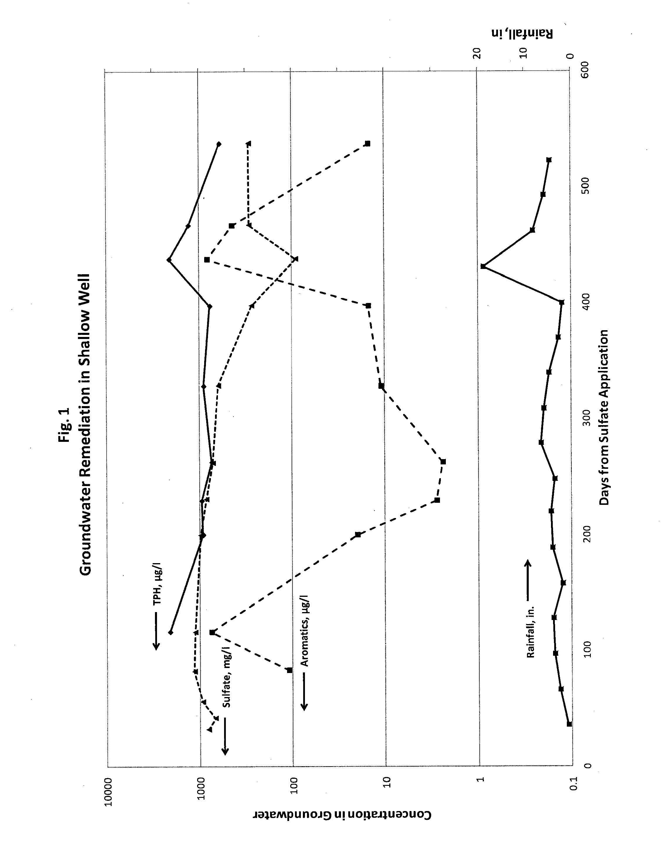
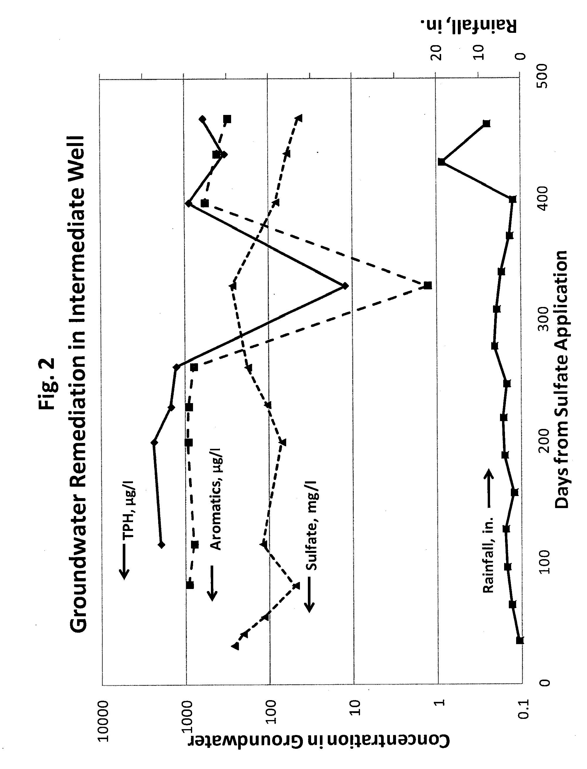
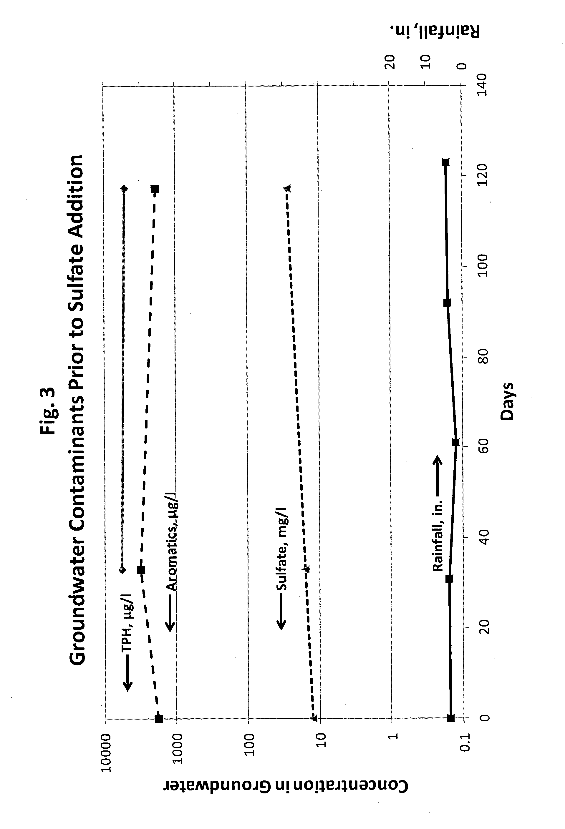
[0040]A vacant site, with no surface infrastructure, overlying contaminated groundwater, was selected for treatment. The aquifer at this site had a hydraulic conductivity of greater than 10−3 cm / sec. At this site, 650 pounds of gypsum was land applied to a 50 ft×50 ft area of the site, and irrigated with 25,000 gal of water over 8 days. Following this application, groundwater from the monitoring wells in the pilot area was periodically sampled. These wells included a shallow well at a depth of 1.5 to 8.5 ft below ground surface and an intermediate well at 8.5 ft to 13.5 ft below ground surface. Water samples from each level were periodically analyzed for sulfate, aromatics and total petroleum hydrocarbons (TPH, typically in the C6 to C12 range) to evaluate the effectiveness of the land application in delivering sulfate to the groundwater and its impact on contaminant concentrations.

[0041]FIG. 1 shows the changes in sulfate, aromatics and TPH concentrations in the shallow well follow...


PUM

PropertyMeasurementUnit
hydraulic conductivityaaaaaaaaaa
depthaaaaaaaaaa
concentrationaaaaaaaaaa

Abstract

A process is provided for bioremediating petroleum hydrocarbon contaminated groundwater by applying at least one electron acceptor salt to a ground surface overlying the contaminated groundwater. The process includes identifying characteristics of the aquifer, in which the contaminated groundwater is found, to enable treatment of aquifers at a range of depths below the ground surface.

Description

CROSS REFERENCE TO RELATED APPLICATION[0001]This application claims the benefit of U.S. patent application Ser. No. 61 / 486,614, filed on May 16, 2011, the entire contents of which is incorporated herein by reference.BACKGROUND OF THE INVENTION[0002]The present invention relates to a new and improved bioremediation process for anaerobic biodegradation, detoxification and transformation of organic compounds in contaminated aquifers. Bioremediation is a process of either promoting or introducing organisms, plants or other flora or fauna to break down or use the organic compounds.[0003]During biodegradation of petroleum hydrocarbons including BTEX compounds (which include benzene, toluene, ethylbenzene and xylene isomers) in groundwater, micro-organisms use dissolved BTEX as an electron donor and rely on a variety of terminal electron accepting processes (TEAP) such as aerobic oxidation, nitrate reduction, iron (III) reduction and sulfate reduction to generate energy and produce new bio...

Claims


Application Information

Patent Timeline
Patent Type & Authority Applications(United States)
IPC IPC(8): C02F3/00
CPCB09C1/002C02F3/28C02F2101/32C02F2305/06C02F2209/15C02F2209/19C02F2101/322
Inventor KOLHATKAR, RAVINDRA VASANT
Owner CHEVROU USA INC
Why Eureka
Try Eureka