Photodetector

a technology of photodetector and detector, which is applied in the field of photodetector, can solve the problems of narrowed detection range and pronounced problem, and achieve the effect of preventing the narrowing of the detection range of ligh

Active Publication Date: 2013-01-17
SEMICON ENERGY LAB CO LTD
View PDF9 Cites 4 Cited by
  • Summary
  • Abstract
  • Description
  • Claims
  • Application Information

AI Technical Summary

Benefits of technology

[0012]According to an embodiment of the present invention, a range of generable values of data signal can be prevented from narrowing, whereby the detecting range of light can be prevented from narrowing.

Problems solved by technology

That is, the detecting range of light is narrowed, which is a problem.
This problem becomes pronounced particularly when the illuminance of incident light is larger than a reference value.

Method used


Image

  • Photodetector
  • Photodetector
  • Photodetector

Examples


embodiment 1

[0021]In this embodiment, an example of a photodetector is described.

[0022]A structural example of the photodetector in this embodiment is described with reference to FIGS. 1A and 1B.

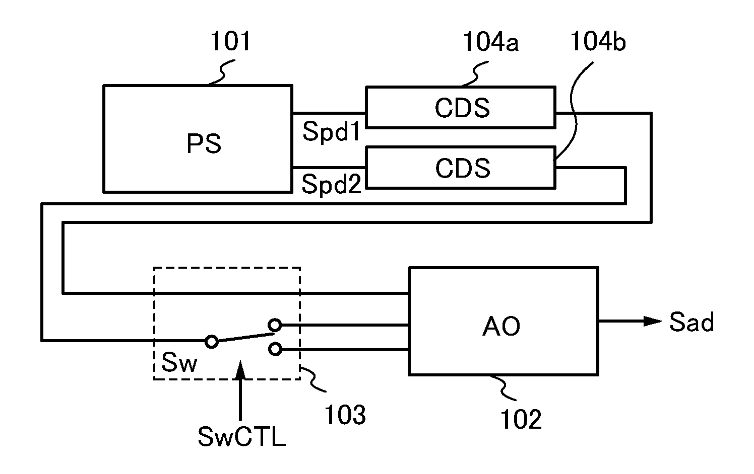
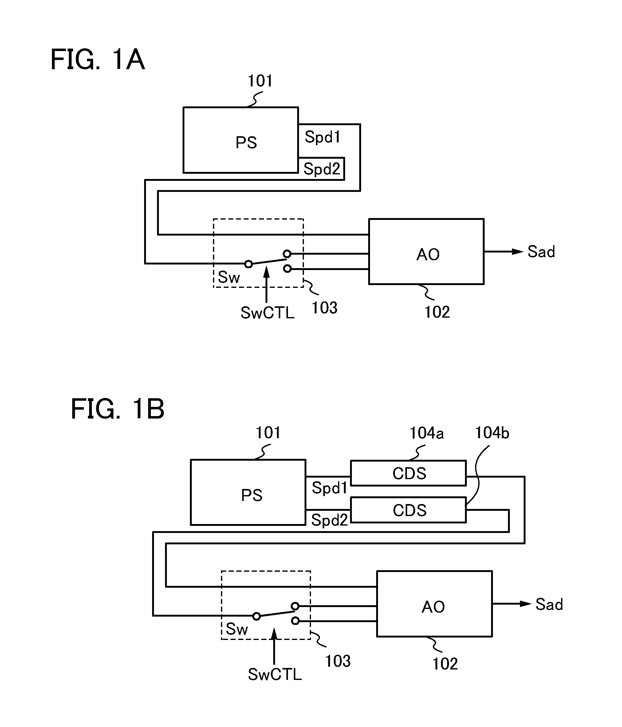
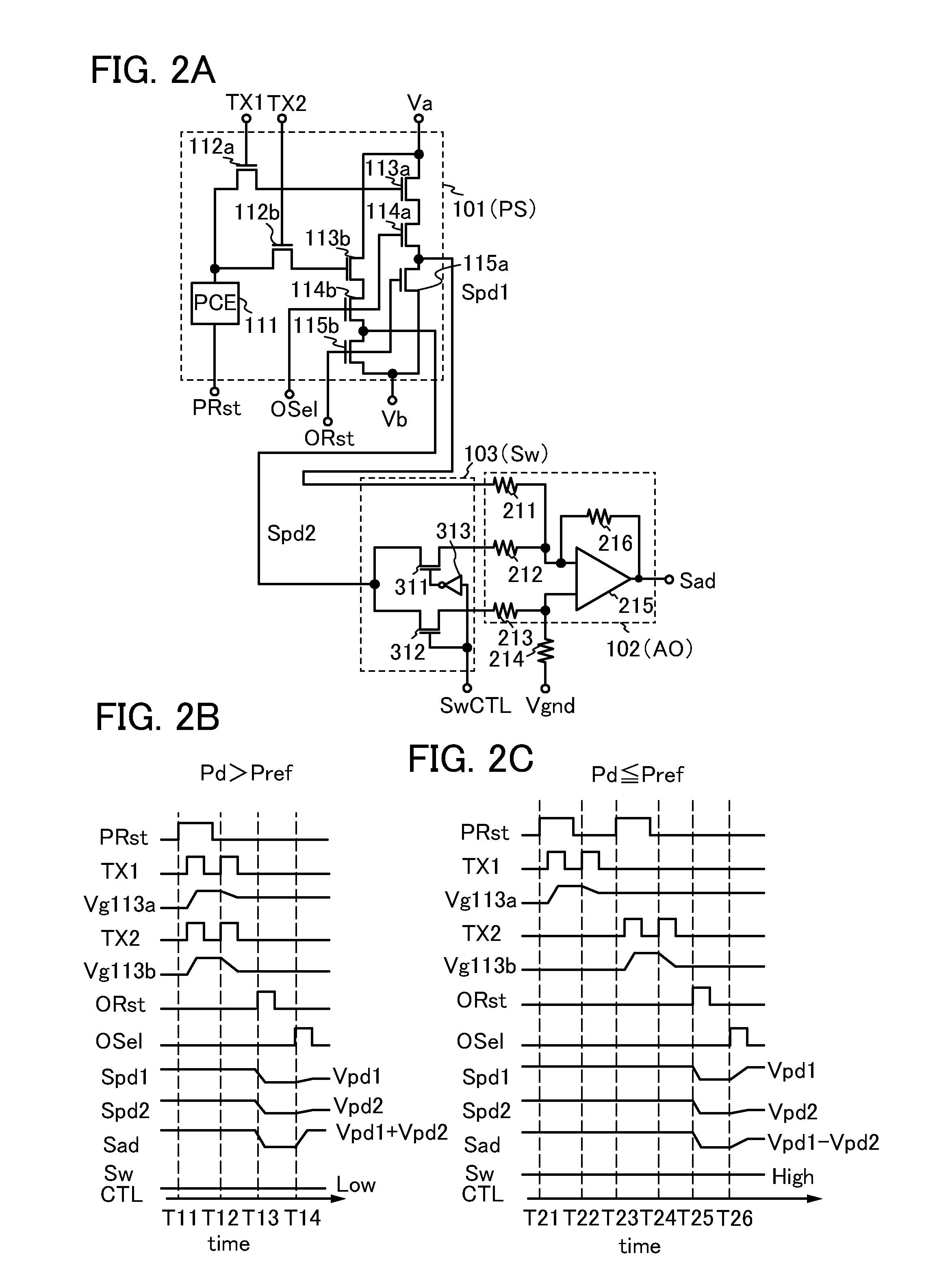
[0023]The photodetector in FIG. 1A includes a photodetector circuit (also referred to as PS) 101, an analog arithmetic circuit (also referred to as AO) 102, and a switching circuit (also referred to as Sw) 103.

[0024]The photodetector circuit 101 has a function of outputting a first optical data signal Spd1 and a second optical data signal Spd2 in which values are determined in accordance with the illuminance of incident light.

[0025]The first optical data signal Spd1 and the second optical data signal Spd2 are input to the analog arithmetic circuit 102. The analog arithmetic circuit 102 has a function of performing an arithmetic processing with the use of the first optical data signal Spd1 and the second optical data signal Spd2 and outputting a potential based on the results of the arithmetic processing...

embodiment 2

[0083]In this embodiment, an example of a photodetector is described.

[0084]First, a structural example of the photodetector in this embodiment is described with reference to FIGS. 3A and 3B. FIGS. 3A and 3B are block diagrams illustrating structural examples of the photodetector in this embodiment.

[0085]A photodetector illustrated in FIG. 3A is an input device which can input data with light. A photodetector illustrated in FIG. 3B is an input / output device which can input data with light and can output data by displaying an image.

[0086]The photodetectors shown in FIGS. 3A and 3B each include a photodetection portion (also referred to as Photo) 401, a control portion (also referred to as CTL) 402, and a data processing portion (also referred to as DataP) 403.

[0087]In addition, the photodetectors shown in FIGS. 3A and 3B each include a photodetection driver circuit (also referred to as PSDRV) 411, a plurality of photodetector circuits (also referred to as PS) 412, a switching circuit ...

embodiment 3

[0125]In this embodiment, examples of electronic devices each including the photodetector described in the above embodiment are described.

[0126]Structural examples of the electronic devices of this embodiment are described with reference to FIGS. 4A to 4D. FIGS. 4A to 4D are schematic views each illustrating a structural example of an electronic device of this embodiment.

[0127]An electronic device illustrated in FIG. 4A is a digital camera. The digital camera illustrated in FIG. 4A includes a housing 1001a, a lens 1002a, a shutter button 1003, a power button 1004, and a flashlight 1005.

[0128]Further, the digital camera includes the photodetector in any of the above embodiments (e.g., the photodetector shown in FIG. 3A) in the housing 1001a. With this structure, incident light is detected by the photodetector through the lens 1002a by pushing the shutter button 1003, so that an image can be taken, for example.

[0129]An electronic device illustrated in FIG. 4B is a video camera. The vi...


PUM


Abstract

Provided is a photodetector in which narrowing of a detecting range of light is suppressed. The photodetector includes a photodetector circuit for outputting a first optical data signal and a second optical data signal in which values are determined in accordance with an illuminance of incident light, an analog arithmetic circuit to which the first optical data signal and the second optical data signal are input and in which an arithmetic processing is performed with the use of the first optical data signal and the second optical data signal, and a switching circuit for switching an arithmetic processing in the analog arithmetic circuit between an addition operation and a subtraction operation of the first optical data signal and the second optical data signal.

Description

BACKGROUND OF THE INVENTION[0001]1. Field of the Invention[0002]An embodiment of the present invention relates to a photodetector.[0003]2. Description of the Related Art[0004]In recent years, technological development of a photodetector which inputs data with the use of a photodetector circuit (also referred to as an optical sensor) capable of generating data having a value corresponding to the illuminance of incident light, a photodetector which inputs data with the use of the photodetector circuit and outputs data in accordance with the input data, and the like has been advanced.[0005]As an example of the photodetector, an image sensor can be given. As examples of the image sensor, a charge coupled device (CCD) image sensor, a complementary metal oxide semiconductor (CMOS) image sensor, and the like can be given (e.g., Patent Document 1).[0006]In the photodetector disclosed in Patent Document 1, in one photodetector circuit, two optical data signals are generated and output to one...

Claims


Application Information

Patent Timeline
Patent Type & Authority Applications(United States)
IPC IPC(8): G01J1/44
CPCG01J1/44H04N5/374H04N5/23212H01L29/7869H04N5/378H04N25/70H04N25/76H04N25/75G01J1/02G01J1/10
Inventor KOZUMA, MUNEHIRO
Owner SEMICON ENERGY LAB CO LTD
Why Eureka
Try Eureka