
Circuit board with thermo-conductive pillar

a technology of thermo-conductive pillars and circuit boards, which is applied in the manufacture of printed circuits, printed circuit aspects, solid-state devices, etc., can solve the problems of overheating, eventually malfunctioning or failing, and interference with temperature exchange, so as to improve led efficiency and method making, the effect of high thermal conductivity

Active Publication Date: 2013-01-24
COFAN USA
View PDF3 Cites 7 Cited by
  • Summary
  • Abstract
  • Description
  • Claims
  • Application Information

AI Technical Summary

Benefits of technology

The present invention improves the temperature control for LED devices. The patent describes a pillar that enhances this efficiency.

Problems solved by technology

When an LED operates in high ambient temperatures, it can overheat and eventually malfunction or fail.
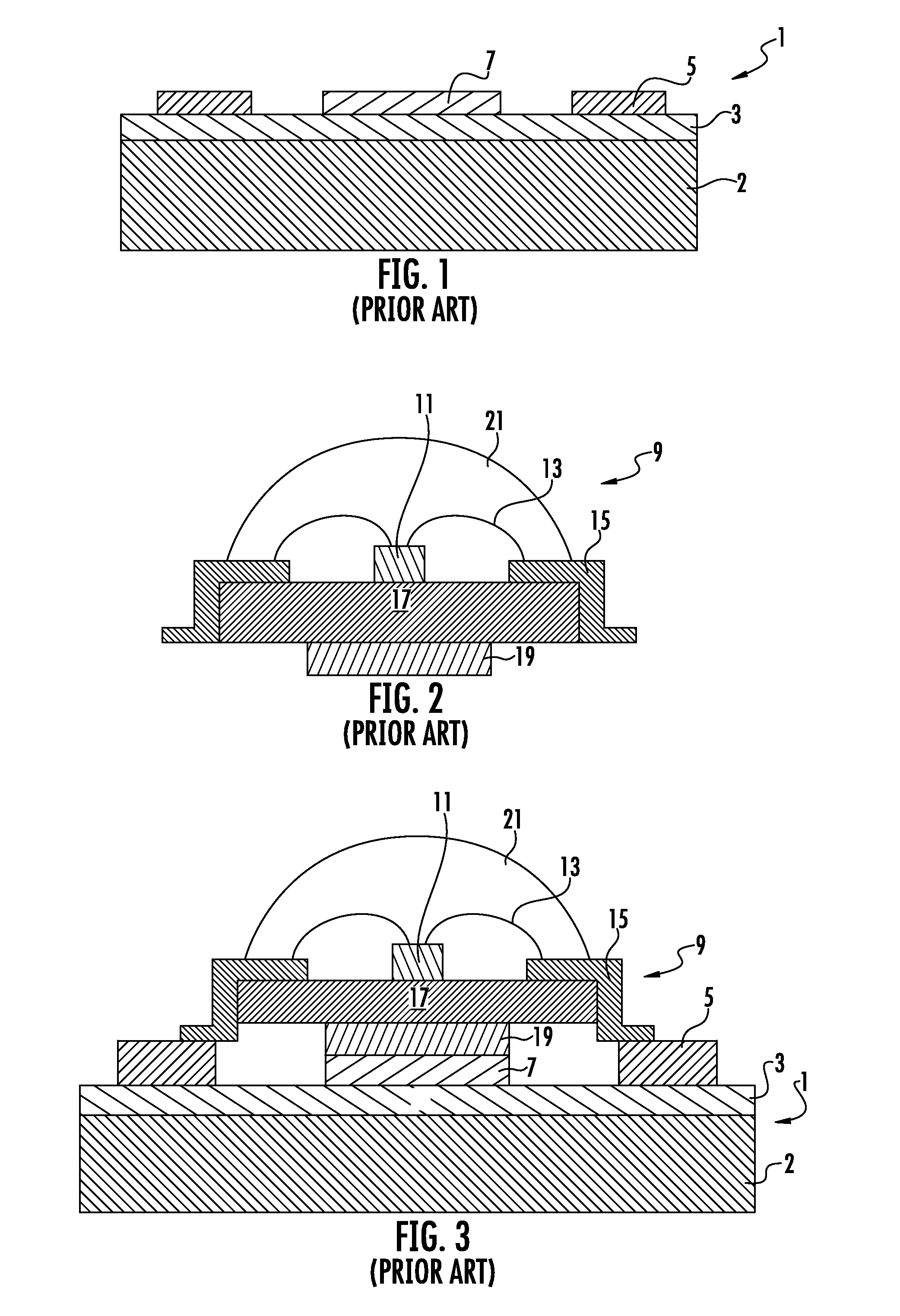
In this prior art device, however, the dielectric layer 3 separates the metal plate 7 from the metal substrate 2 and interferes with temperature exchange.

Method used


Image

  • Circuit board with thermo-conductive pillar
  • Circuit board with thermo-conductive pillar
  • Circuit board with thermo-conductive pillar

Examples


Embodiment Construction

[0023]The present disclosure now will be described more fully with reference to the accompanying drawings, in which some, but not all embodiments of the disclosure are shown. This disclosure may be embodied in many different forms and should not be construed as limited to the embodiments set forth; rather, these example embodiments are provided so that this disclosure will be thorough and complete, and will fully convey the scope of the disclosure to those skilled in the art. Like numbers refer to like elements throughout.

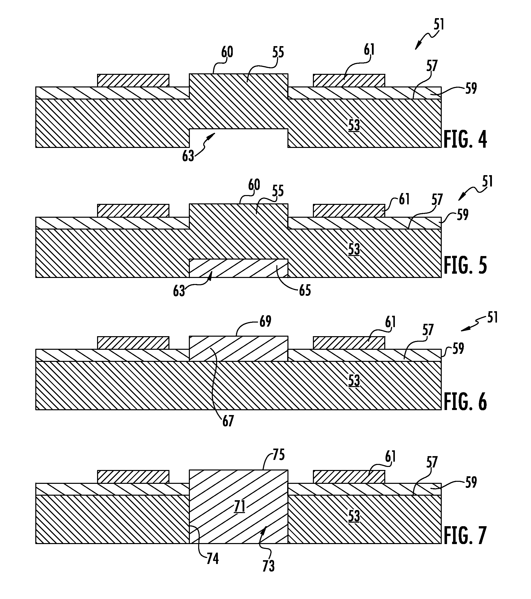
[0024]FIG. 4 depicts a circuit board LED support structure 51 according to some example embodiments of the present invention. In some example embodiments, the circuit board is a metal core printed circuit board (MCPCB).

[0025]In the example embodiment of FIG. 4, the circuit board LED support structure 51 comprises a substrate 53. In some example embodiments, the substrate 53 is made of a material with high thermal conductivity. In some example embodiments, the subst...


PUM

PropertyMeasurementUnit
Structureaaaaaaaaaa
Electrical conductoraaaaaaaaaa

Abstract

An LED device with improved circuit board LED support structure is presented. A top surface of a thermally-conductive substrate of this LED device comprises a thermally-conductive pillar. The pillar is not covered with a dielectric layer and an LED package is arranged directly on the pillar with the LED packages bottom thermally-conductive plate in direct contact with the pillar top surface.

Description

FIELD[0001]The example embodiments of the present invention pertain generally to devices comprising light-emitting diodes (LEDs), including devices comprising surface-mounted LEDs.BACKGROUND[0002]Light-emitting diodes (LEDs) are widely used as a semiconductor lighting source. Generally an LED die is packaged by attaching it to a dielectric substrate, wire-bonding it to electrodes pre-installed on the substrate surface, and covering it with an epoxy “glob-top” to protect the LED die from mechanical damage and contamination, and to improve the LED radiation angle.[0003]Performance of an LED is sensitive to the temperature of the operating environment. When an LED operates in high ambient temperatures, it can overheat and eventually malfunction or fail. The LED efficiency can be increased by improving thermal dissipation from the LED die. This can be achieved by the use of a circuit board with a high thermally-conductive substrate, such as a Metal Core Printed Circuit Board (MCPCB).[00...

Claims


Application Information

Patent Timeline
IPC IPC(8): H01L33/62H05K3/00H05K1/11
CPCH05K1/05H05K2201/0385H05K1/0203H05K2201/10106H05K2201/09054H05K2201/10416H01L2224/48091H05K2201/10969H01L33/642Y10T29/49124H01L33/62H05K2201/09045H05K1/0306H05K1/0204H01L2924/00014
Inventor HAN, CHANGNGUYEN, LAC
Owner COFAN USA
Learn More