Electromechanical apparatus, robot, and moving body

a technology of electromechanical apparatus and moving body, which is applied in the manufacture of stator/rotor bodies, electric devices, cycles, etc., can solve the problems of eddy current generation heat generation and loss due to eddy current produced in the stator ring, and the amount of eddy current, so as to reduce the amount of heat generation and loss and improve the efficiency of the electromechanical apparatus.

Inactive Publication Date: 2013-01-24
SEIKO EPSON CORP
View PDF8 Cites 24 Cited by
  • Summary
  • Abstract
  • Description
  • Claims
  • Application Information

AI Technical Summary

Benefits of technology

[0006]An advantage of some aspects of the invention is to reduce the amounts of heat generati...

Problems solved by technology

In the technology of the related art, however, the stator ring is made of stainless steel, which is a conductor, in consideration of strength and heat dissipation, but heat generation and loss due to eddy current produced in the stator ring are not well considered.
That is, to dissipate heat generated in the stator ring, it is preferable to use a material having good heat conductivity, but ...

Method used


Image

  • Electromechanical apparatus, robot, and moving body
  • Electromechanical apparatus, robot, and moving body
  • Electromechanical apparatus, robot, and moving body

Examples


Embodiment Construction

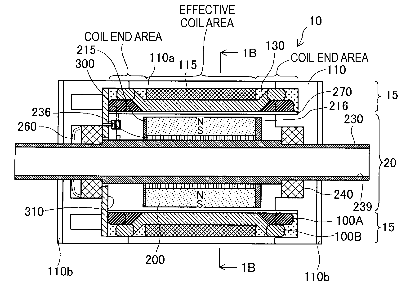
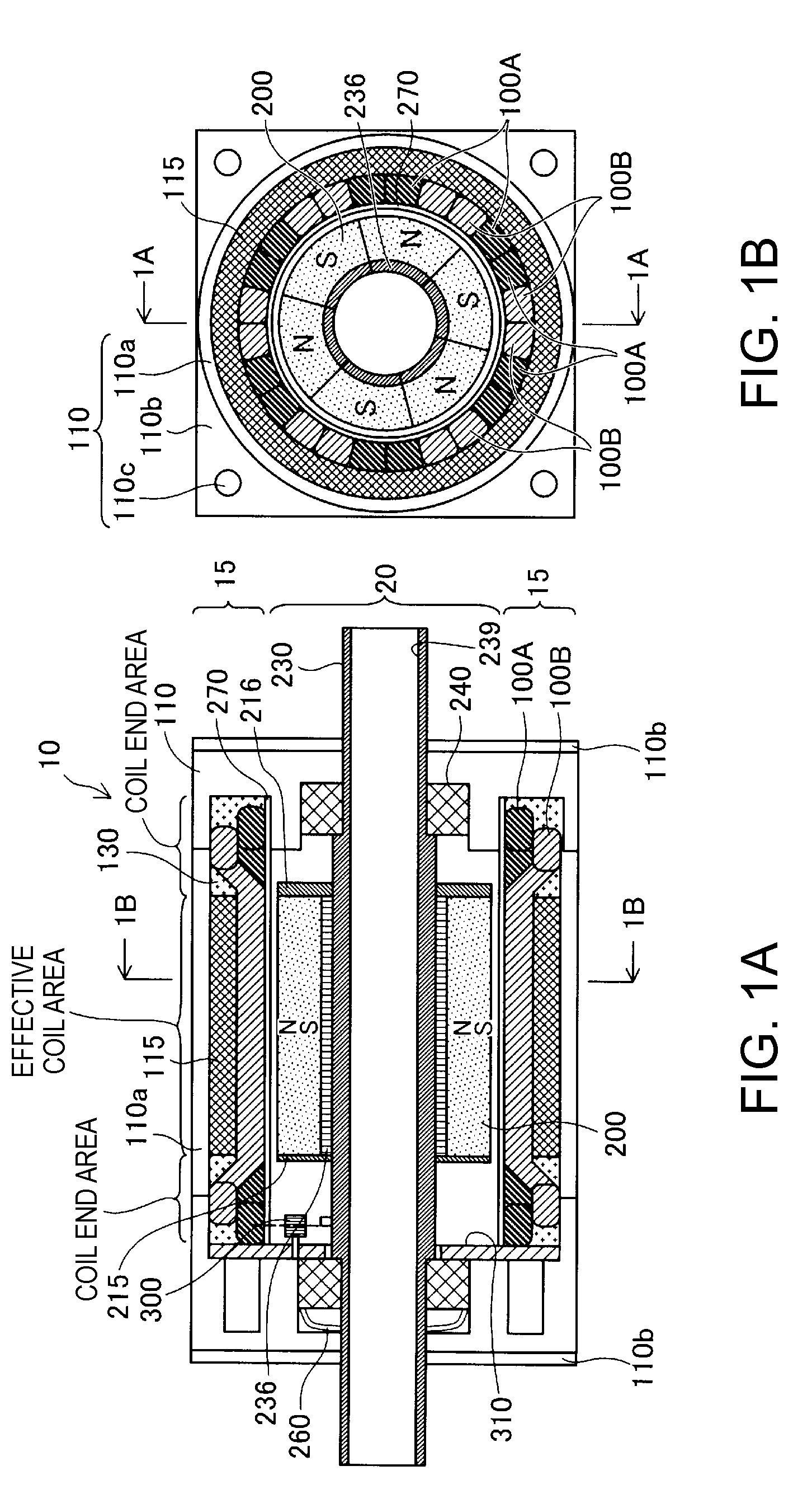
[0039]FIGS. 1A and 1B are descriptive diagrams showing the configuration of a coreless motor. FIG. 1A is a schematic cross-sectional view of a coreless motor 10 taken along a plane parallel to a central shaft 230 (taken along line 1A-1A in FIG. 1B), and FIG. 1B is a schematic cross-sectional view of the coreless motor taken along a plane perpendicular to the central shaft 230 (taken along line 1B-1B in FIG. 1A).

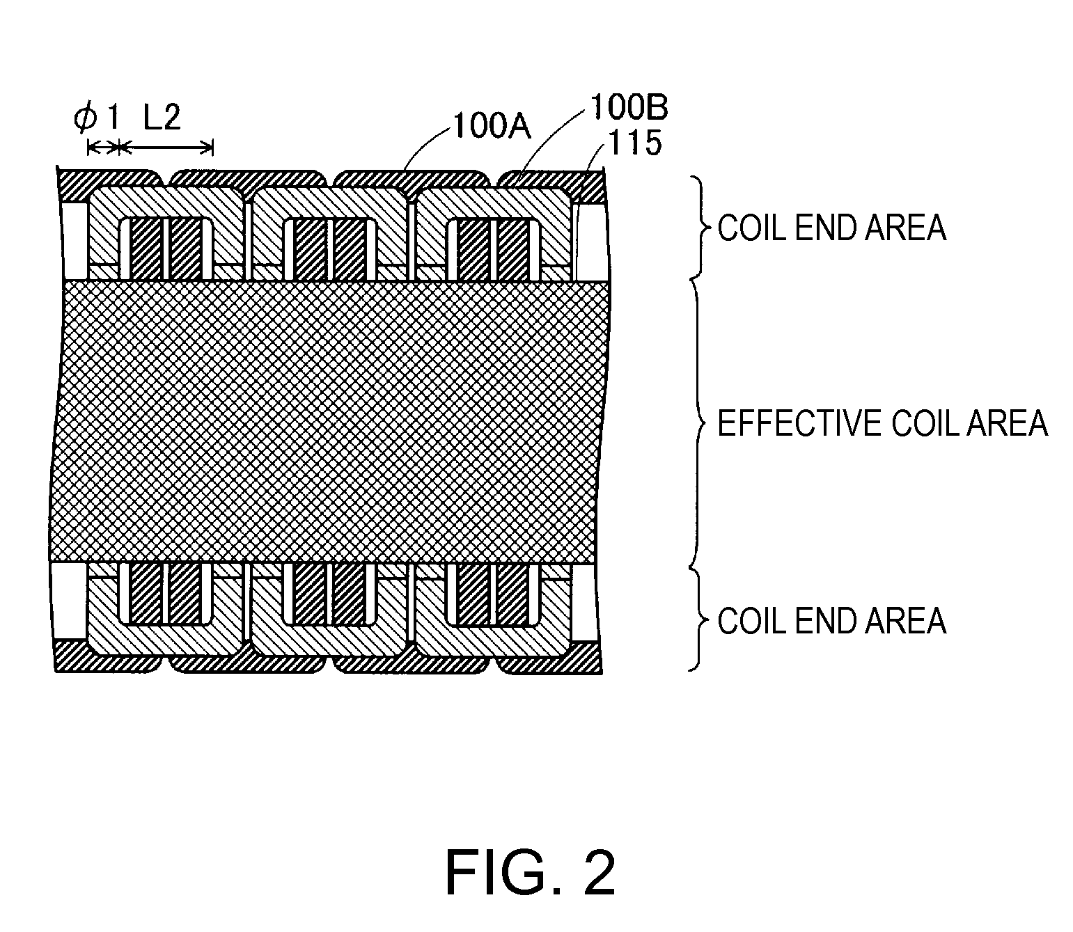
[0040]The coreless motor 10 is an inner-rotor motor including a substantially hollow cylindrical stator 15 disposed in an outer portion thereof and a substantially hollow cylindrical rotor 20 disposed in an inner portion thereof. The stator 15 includes electromagnetic coils 100A and 100B, a pipe member 270, a casing 110, a coil back yoke 115, and a magnetic sensor 300. The rotor 20 includes a central shaft 230, a permanent magnet 200, magnet side yokes 215 and 216, a magnet back yoke 236, a bearing 240, and a wave spring washer 260.

[0041]The central shaft 230 is disposed at t...


PUM


Abstract

An electromechanical apparatus includes: a rotor including a central shaft and permanent magnets disposed around a cylindrical surface along an outer circumference of the central shaft, and a stator including hollow electromagnetic coils disposed around a cylindrical surface along an outer circumference of the permanent magnets and a pipe member having a hollow cylindrical shape and disposed between the permanent magnets and the electromagnetic coils, wherein the pipe member is made of a carbon fiber reinforced plastic, and the carbon fiber reinforced plastic is formed by weaving carbon fiber bundles formed of bundled carbon fibers.

Description

BACKGROUND[0001]1. Technical Field[0002]The present invention relates to an electromechanical apparatus, a robot, and a moving body.[0003]2. Related Art[0004]There is a known technology for preventing stator coils in a slotless motor from separating from a housing even when a shaft of the slotless motor is rotated at an ultra-high speed (JP-A-2000-50557, for example). The slotless motor includes a stator ring having an outer circumferential surface pressed against the stator coils and an inner circumferential surface maintained separate from magnets by a predetermined gap and disposed between the magnets and the stator coils and a fixing member that fixes the stator ring to a housing cap fixedly attached to both ends of the housing and maintains the separation distance between the outer circumferential surface of the magnets and the inner circumferential surface of the stator ring.[0005]In the technology of the related art, however, the stator ring is made of stainless steel, which ...

Claims


Application Information

Patent Timeline
IPC IPC(8): H02K3/47
CPCG01R31/34H02K21/14H02K3/42H02K15/02H02K5/128H02K7/003H02K9/22H02K3/46B60L3/0061B60L2200/12B60L2200/26B60L2220/14B60L2220/16B60L2240/425B60L2220/50B60L50/20Y02T10/64H02K9/223
Inventor TAKEUCHI, KESATOSHI
Owner SEIKO EPSON CORP
Why Eureka
Try Eureka