
Virtual GPU

Active Publication Date: 2013-01-24
APPLE INC
View PDF8 Cites 32 Cited by
  • Summary
  • Abstract
  • Description
  • Claims
  • Application Information

AI Technical Summary

Benefits of technology

The patent describes a way to make computer graphics processing units (GPUs) more efficient and effective at executing multiple tasks simultaneously. This is done by implementing multiple virtual GPUs that can share the same hardware and store computation results separately. This reduces the need for costly context switching between programs and allows for better control over execution and resource allocation. Overall, this technology improves the performance and efficiency of GPUs in processing tasks, especially in mobile devices.

Problems solved by technology

A GPU may sometimes experience “down time” (stall periods) in which one or more execution units do not perform any calculations.
Thus, at times, one or more GPU execution units may be idle.
Further, when a first program is being executed by a GPU, a second program may have to wait.
Although it would be advantageous for the second program to use idle GPU execution units while the first program is stalled, the overhead cost of switching to the second program may be prohibitively expensive.
That is, setting up the GPU to execute the second program while the first program is stalled may take so much time and effort (i.e., power consumption) that it is not worth the trouble.
While the first program stalls, GPU execution units may thus remain idle.
Accordingly, GPU execution may be inefficient, especially in environments where multiple computing tasks are being performed.
Virtual GPUs may provide an advantage over context switching, which may have high costs.
These copying operations take time and consume power (which may cause a particularly negative impact on battery powered mobile devices).
But while context switching only on frame or polygon boundaries can be less costly, this may result in poor granularity control.
The stall period may be short enough that a full context switch would be cost prohibitive.
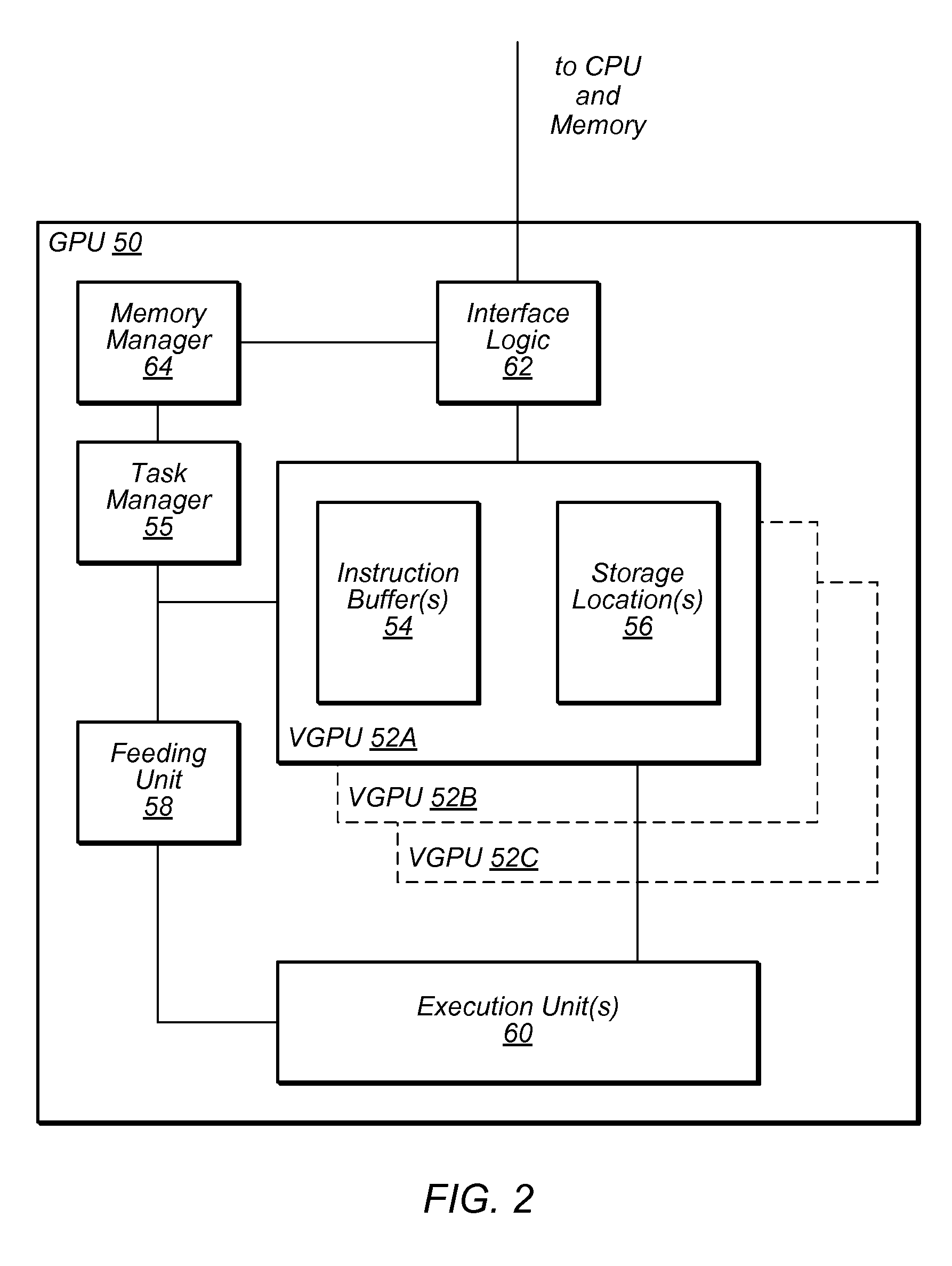
However, the lower cost of switching between virtual GPUs may allow different instructions (for a different virtual GPU) to be executed instead of having the execution unit sit idle.

Method used


Image

  • Virtual GPU
  • Virtual GPU
  • Virtual GPU

Examples


Embodiment Construction

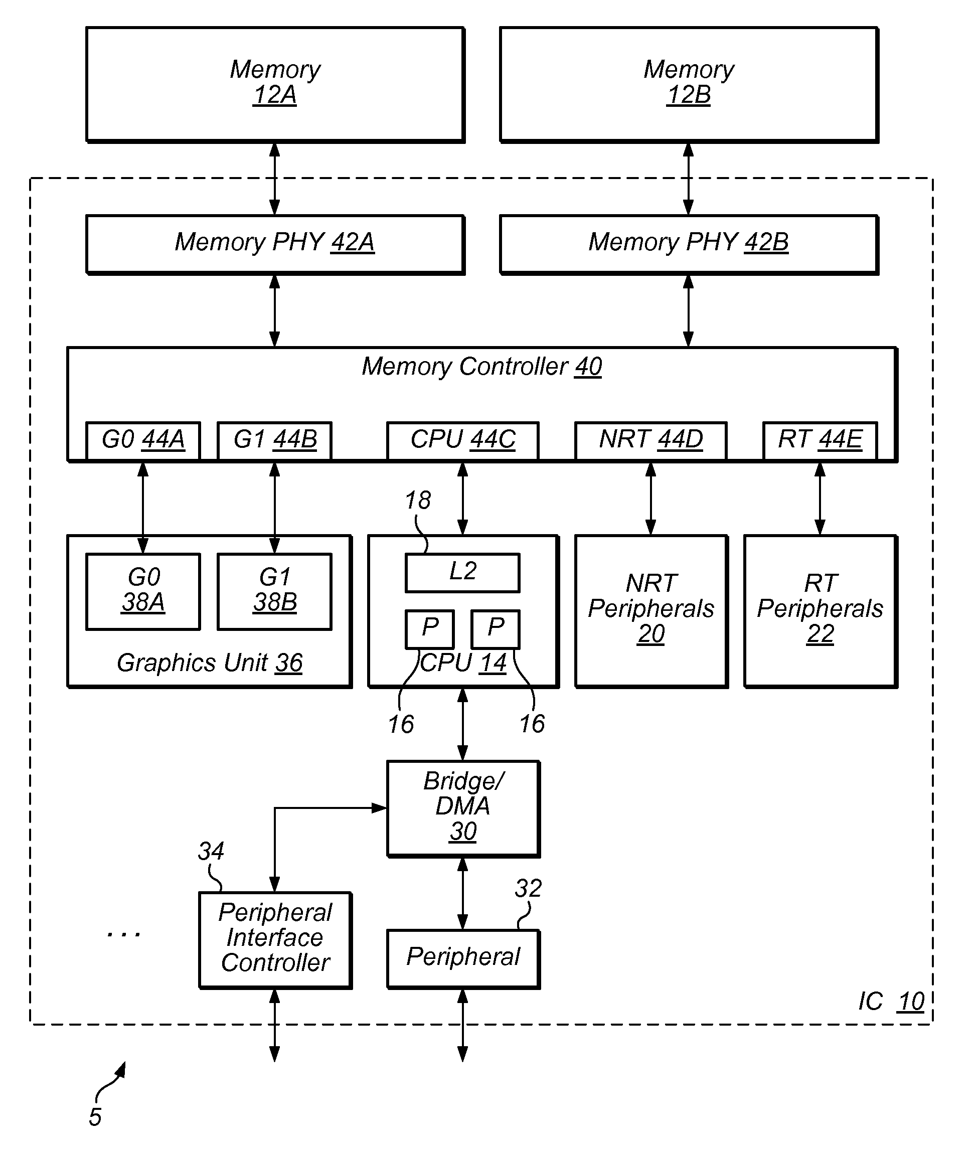
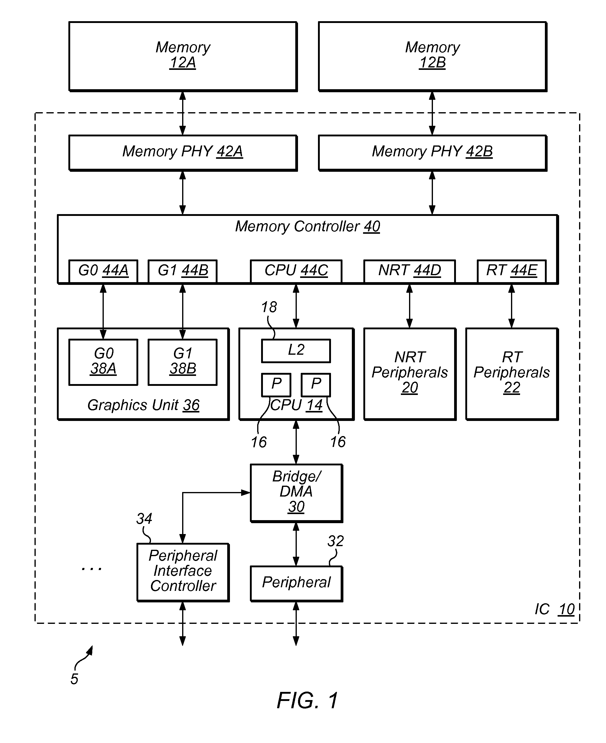
[0019]This specification includes references to “one embodiment” or “an embodiment.” The appearances of the phrases “in one embodiment” or “in an embodiment” do not necessarily refer to the same embodiment. Particular features, structures, or characteristics may be combined in any suitable manner consistent with this disclosure.

[0020]The following paragraphs provide definitions and / or context for terms found in this disclosure (including the appended claims):

[0021]“Comprising.” This term is open-ended. As used herein, this term does not foreclose additional structure or steps. Consider a claim that recites: “An apparatus comprising a graphics processing unit (GPU) . . . .” Such a claim does not preclude the apparatus from including additional components (e.g., a central processing unit, a memory controller, interface circuitry, etc.).

[0022]“Configured To.” Various units, circuits, or other components may be described or claimed as “configured to” perform a task or tasks. In such con...


PUM


Abstract

Techniques and structures relating to virtual graphics processing units (VGPUs) are disclosed. A VGPU may appear to software as an independent hardware GPU. However, two or more VGPUs can be implemented on the same GPU through the use of control structures and by duplicating some (but not all) hardware elements of the GPU. For example, additional registers and storage space may be added in a GPU supporting multiple VGPUs. Different execution priorities may be set for tasks and threads that correspond to the different supported VGPUs. Memory address space for the VGPUs may also be managed, including use of virtual address space for different VGPUs. Halting and resuming execution of different VGPUs may allow for finer-grained execution control, and for better GPU efficiency.

Description

RELATED APPLICATIONS[0001]This application claims the benefit of U.S. Provisional Application 61 / 509,089, filed Jul. 18, 2011, titled “Virtual GPU,” which is herein incorporated by reference in its entirety.BACKGROUND[0002]1. Technical Field[0003]This disclosure relates to graphical processing units (GPUs), and more particularly, relates to structures and techniques allowing for efficient execution of multiple GPU commands.[0004]2. Description of the Related Art[0005]GPUs can be used to execute a variety of computing tasks. A GPU can calculate pixels to be displayed on a screen, for example, and may also perform other intensive operations such as animation rendering and general vector math.[0006]A GPU may sometimes experience “down time” (stall periods) in which one or more execution units do not perform any calculations. Down time can occur when accessing memory, for example, because an execution unit is waiting for new data to arrive. Thus, at times, one or more GPU execution unit...

Claims


Application Information

Patent Timeline
IPC IPC(8): G06T1/00
CPCG06F9/5077G06T1/20G06T1/60
Inventor DREBIN, ROBERT A.WANG, JAMES
Owner APPLE INC
Learn More