Lighting apparatus with a light source comprising light emitting diodes

Active Publication Date: 2013-01-24
CONSUMER LIGHTING (U S) LLC
View PDF6 Cites 16 Cited by
  • Summary
  • Abstract
  • Description
  • Claims
  • Application Information

AI Technical Summary

Benefits of technology

The present invention is about a lighting apparatus that looks like an incandescent lamp and has good heat dissipation to prevent overheating. The technical effects of this invention are better heat management and a more consistent optical intensity compared to traditional incandescent lamps.

Problems solved by technology

Unfortunately, LED-based devices are highly directional by nature.
Thus, although superior in performance, the optical intensity of many commercially-available LED lamps intended as incandescent replacements is not consistent with the optical intensity of incandescent lamps.
Yet another challenge with solid-state technology is the need to adequately dissipate heat.
However, the heat sink may block light that the LED device emits and hence further limits the ability to generate light of uniform optical intensity.
Physical constraints such as regulatory limits that define maximum dimensions for all lamp components, including light sources, further limit that ability to properly dissipate heat.

Method used


Image

  • Lighting apparatus with a light source comprising light emitting diodes
  • Lighting apparatus with a light source comprising light emitting diodes
  • Lighting apparatus with a light source comprising light emitting diodes

Examples


example

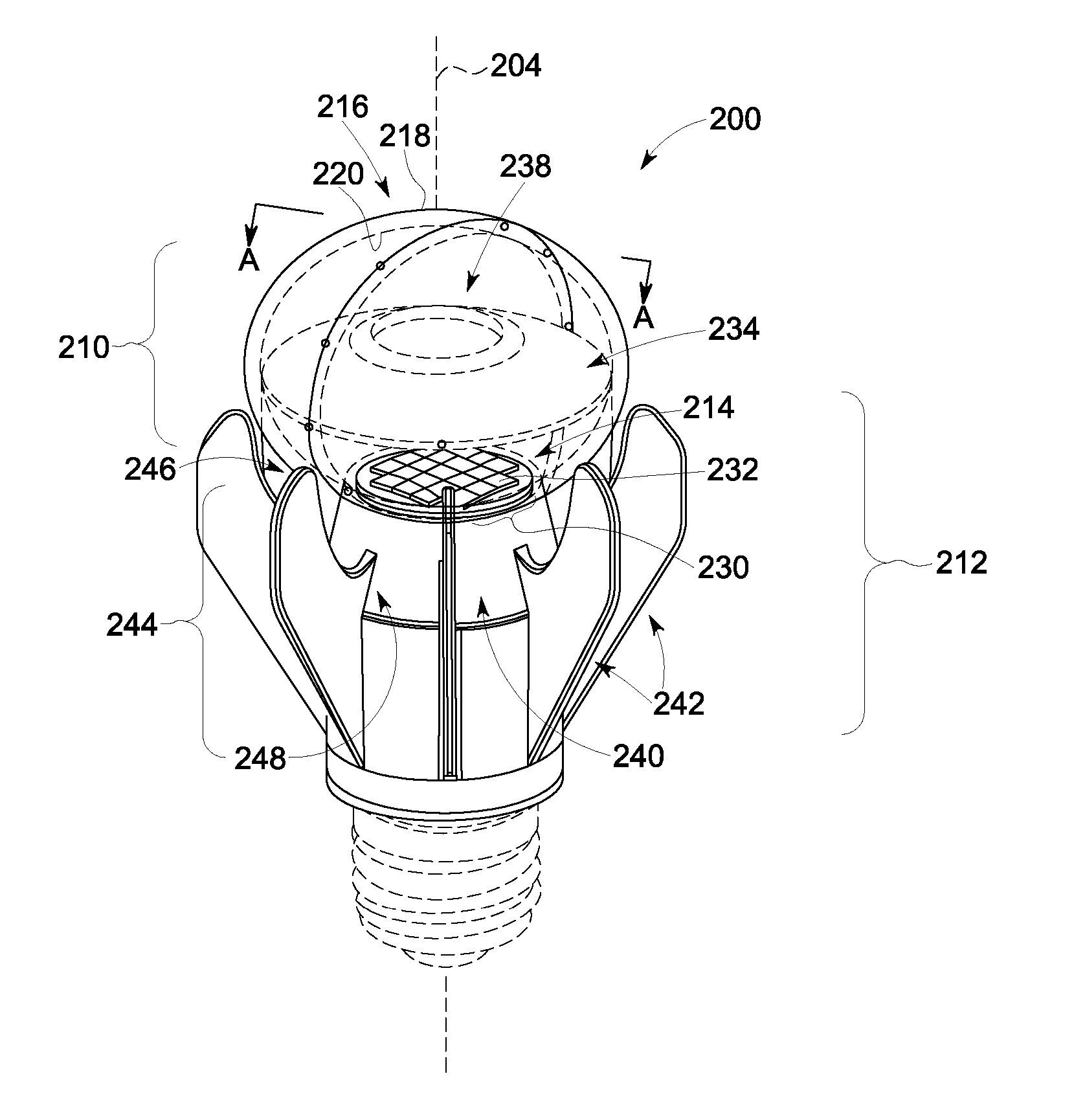
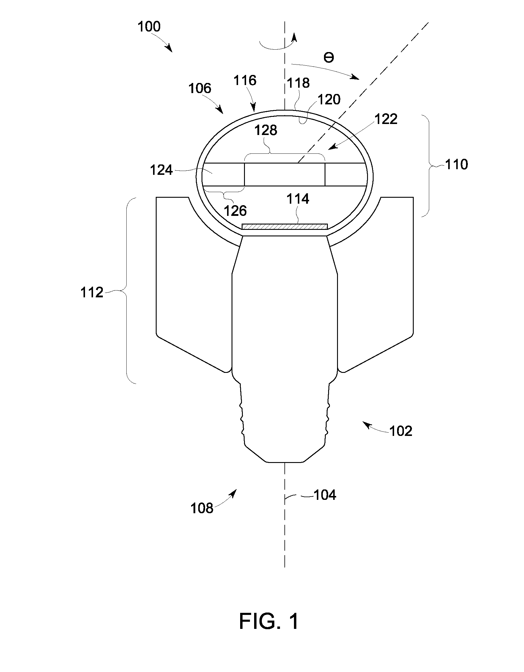
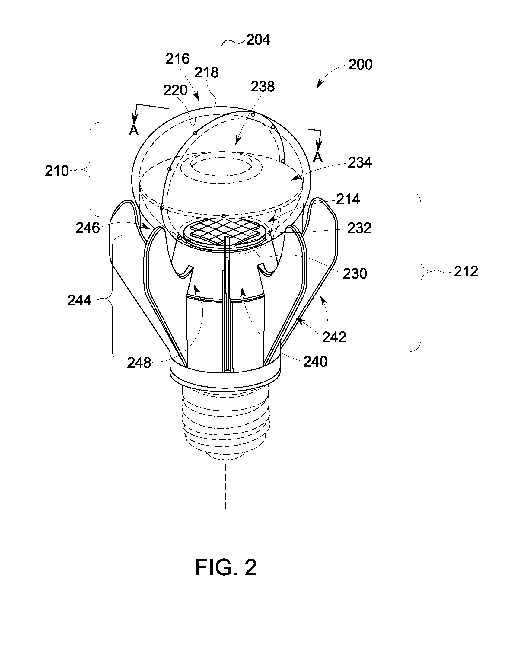
[0051]In one embodiment, a lighting apparatus (e.g., the lighting apparatus 100, 200 of FIGS. 1, 2, 3, 4, 5, 6, and 7) comprises the following:

[0052]An example of an envelope (e.g., the envelope 116, 216 of FIGS. 1, 2, 3, 4, and 5) comprising a Teijin ML5206 low loss diffuser having a spheroidal shape with dimensions of 53 mm×53 mm×39 mm.

[0053]An example of a reflector element (e.g., the reflector element 124, 224 of FIGS. 1, 2, 3, 4, 5, 6, and 7). The reflector element comprises a cone element (e.g., the cone element 234 of FIGS. 4, 5, 6, and 7) comprising a slotted polycarbonate cone with high-reflectance paint and / or high-reflectance self-adhesive laminates and / or integral molded high-reflectance white plastics. The reflector element also comprises an aperture element (e.g., the aperture element 238 of FIGS. 3, 4, 5, 6, and 7) comprising an 80° surface diffuser center aperture, wherein 80° is the full-width at half-maximum (FWHM) of the intensity distribution of light scattered b...


PUM


Abstract

Embodiments of a lighting apparatus with a light source using one or more light emitting diodes (LEDs) to generate light. In one embodiment, the lighting apparatus comprises a light diffusing assembly that generates an optical intensity profile consistent with incandescent lamps. The light diffusing assembly comprises an envelope and a reflector element having frusto-conical member and an aperture element disposed therein. The lighting apparatus can also comprise a heat dissipating assembly with a plurality of heat dissipating elements disposed annularly about the envelope. In one example, the heat dissipating elements are spaced apart from the envelope to promote convective heat dissipation.

Description

BACKGROUND[0001]The subject matter of the present disclosure relates to lighting and lighting devices and, more particularly, to embodiments of a lighting apparatus using light-emitting diodes (LEDs), wherein the embodiments exhibit an optical intensity distribution consistent with common incandescent lamps.[0002]Incandescent lamps (e.g., integral incandescent lamps and halogen lamps) mate with a lamp socket via a threaded base connector (sometimes referred to as an “Edison base” in the context of an incandescent light bulb), a bayonet-type base connector (i.e., bayonet base in the case of an incandescent light bulb), or other standard base connector. These lamps are often in the form of a unitary package, which includes components to operate from standard electrical power (e.g., 110 V and / or 220 V AC and / or 12 VDC). In the case of incandescent and halogen lamps, these components are minimal, as the lamp comprises an incandescent filament that operates at high temperature and effici...

Claims


Application Information

Patent Timeline
IPC IPC(8): F21V29/00F21V7/04F21V7/00
CPCF21K9/135F21V7/04F21V29/20F21V29/773F21V3/02F21V7/041F21Y2101/02F21K9/50F21K9/232F21K9/60F21Y2115/10F21K9/68
Inventor CHINNIAH, JEYACHANDRABOSECHOWDHURY, ASHFAQUL ISLAMALLEN, GARY ROBERTMARTINS, JEREMIAS ANTHONYROTELLA, ANTHONY
Owner CONSUMER LIGHTING (U S) LLC
Why Eureka
Try Eureka