Optical oscillation device and recording apparatus
an optical oscillation device and recording device technology, applied in the field of optical oscillation devices and recording devices, can solve problems such as noise, oscillation wavelength changes, and output variation or nois
- Summary
- Abstract
- Description
- Claims
- Application Information
AI Technical Summary
Benefits of technology
Problems solved by technology
Method used
Image
Examples
first embodiment (
2. First Embodiment (Control Example of Oscillation Frequency by Direct Current During Oscillation Period)
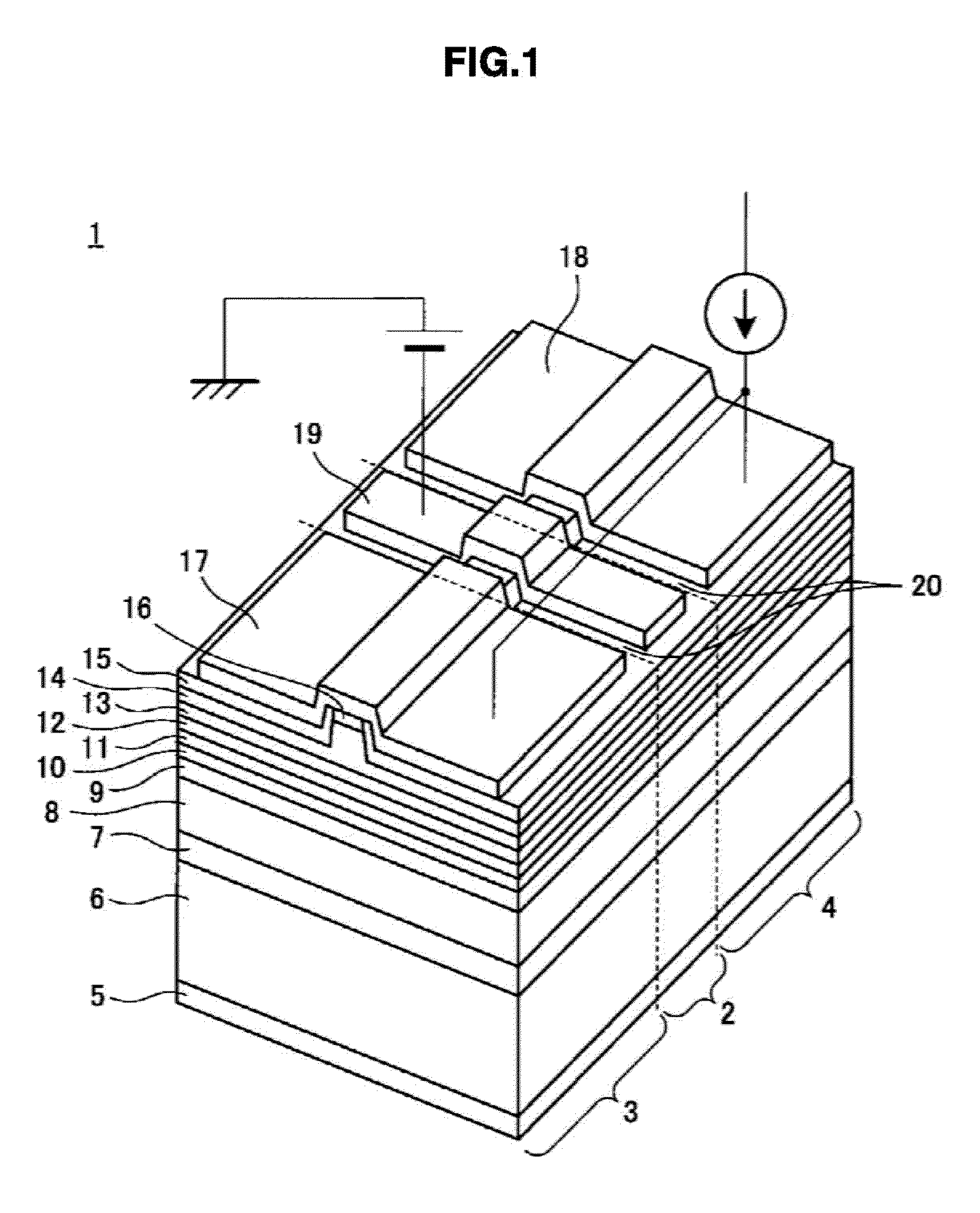
[0108]A recording apparatus including the self-excited oscillation semiconductor laser 1 having the above-described characteristics will be described below.
[0109]FIG. 11 is a schematic diagram illustrating the configuration of a recording apparatus 100 according to a first embodiment. The recording apparatus 100 according to this embodiment includes an optical oscillation unit 110 and an objective lens 41 that condenses the oscillated light beam emitted from the optical oscillation unit 110 on an optical recording medium 43.
[0110]The recording apparatus 100 according to this embodiment includes a mirror 40 that guides the oscillated light beam emitted from the optical oscillation unit 110 toward the objective lens 41 and a spindle motor 42 that rotates an optical recording medium 43 in an in-plane direction of the optical recording medium 43.
[0111]The optical oscillation unit 11...
second embodiment (
3. Second Embodiment (Control Example of Oscillation Frequency of Direct Current Voltage During Oscillation Period)
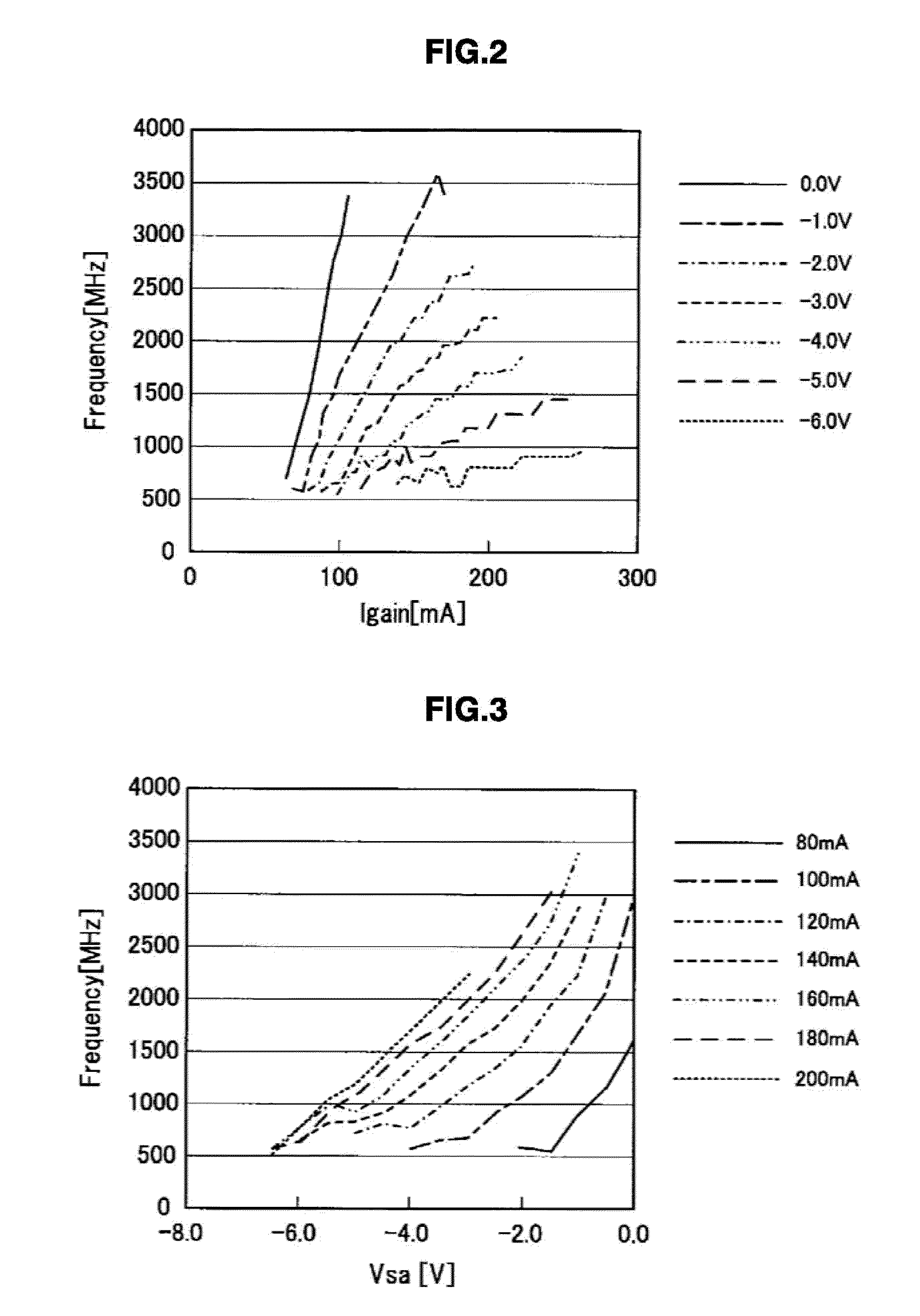
[0132]In the first embodiment, the oscillation frequency of the self-excited oscillation semiconductor laser 1 was controlled using the value of the gain current during the oscillation period. However, as shown in FIG. 3, the oscillation frequency of the self-excited oscillation semiconductor laser 1 is also changed using the value of the reverse bias voltage. Hereinafter, an example of a recording apparatus that controls the oscillation frequency of the self-excited oscillation semiconductor laser 1 using a reverse bias voltage will be described.
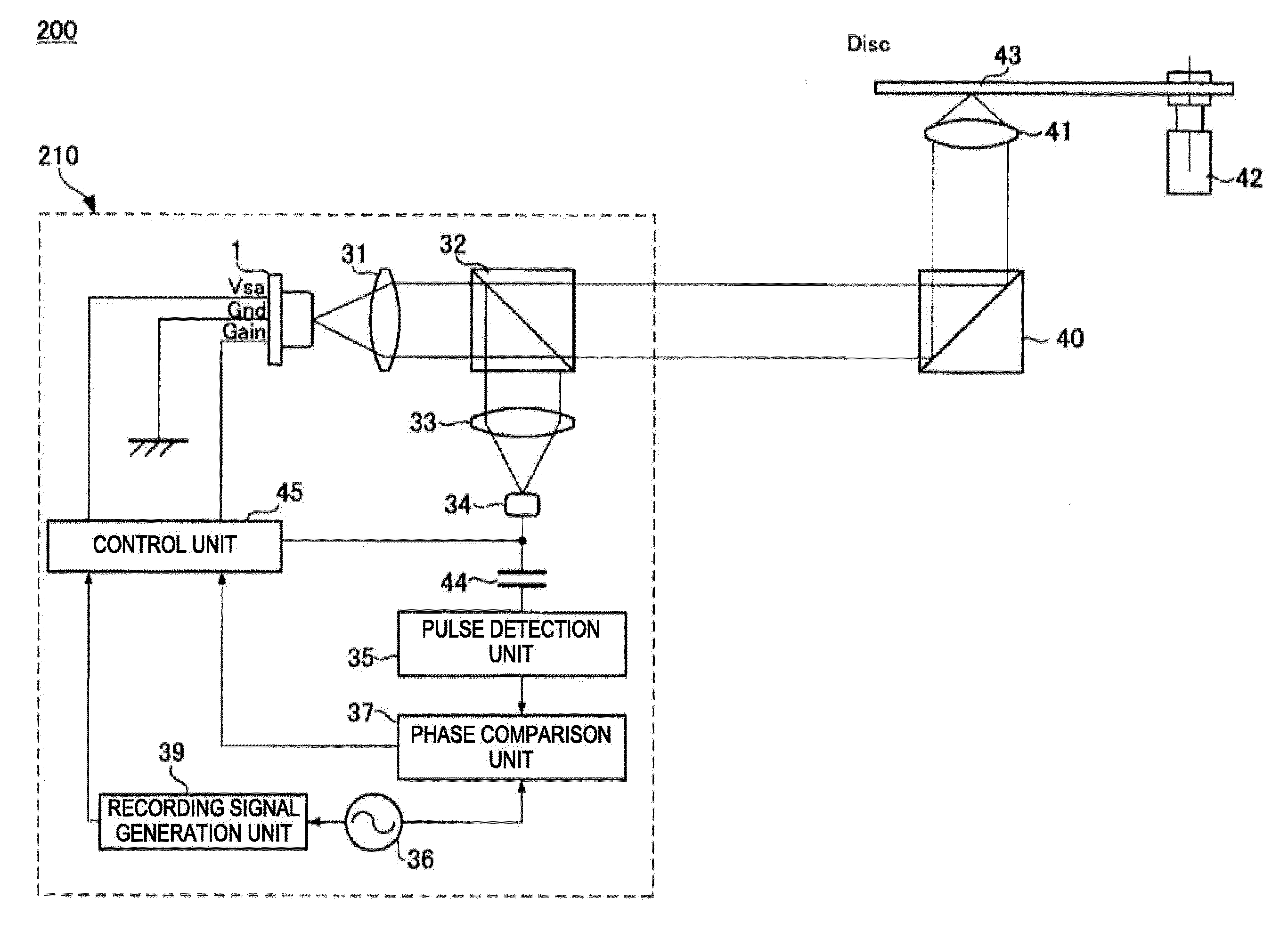
[0133]FIG. 12 is a schematic diagram illustrating the configuration of a recording apparatus 200 according to a second embodiment. The same reference numerals are given to units corresponding to the units of the first embodiment (see FIG. 11), and the description thereof will not be repeated.
[0134]The recording apparatus 200 ac...
PUM
| Property | Measurement | Unit |
|---|---|---|
| frequencies | aaaaa | aaaaa |
| frequencies | aaaaa | aaaaa |
| frequency | aaaaa | aaaaa |
Abstract
Description
Claims
Application Information
 - R&D
- Intellectual Property
- Life Sciences
- Materials
- Tech Scout
- Unparalleled Data Quality
- Higher Quality Content
- 60% Fewer Hallucinations
Browse by: Latest US Patents, China's latest patents, Technical Efficacy Thesaurus, Application Domain, Technology Topic, Popular Technical Reports.
© 2025 PatSnap. All rights reserved.Legal|Privacy policy|Modern Slavery Act Transparency Statement|Sitemap|About US| Contact US: help@patsnap.com


