Power control unit
a power control unit and power technology, applied in non-electric variable control, process and machine control, instruments, etc., can solve problems such as no consideration, and achieve the effect of efficient supply, and efficient generation of electric power
- Summary
- Abstract
- Description
- Claims
- Application Information
AI Technical Summary
Benefits of technology
Problems solved by technology
Method used
Image

Examples
first embodiment
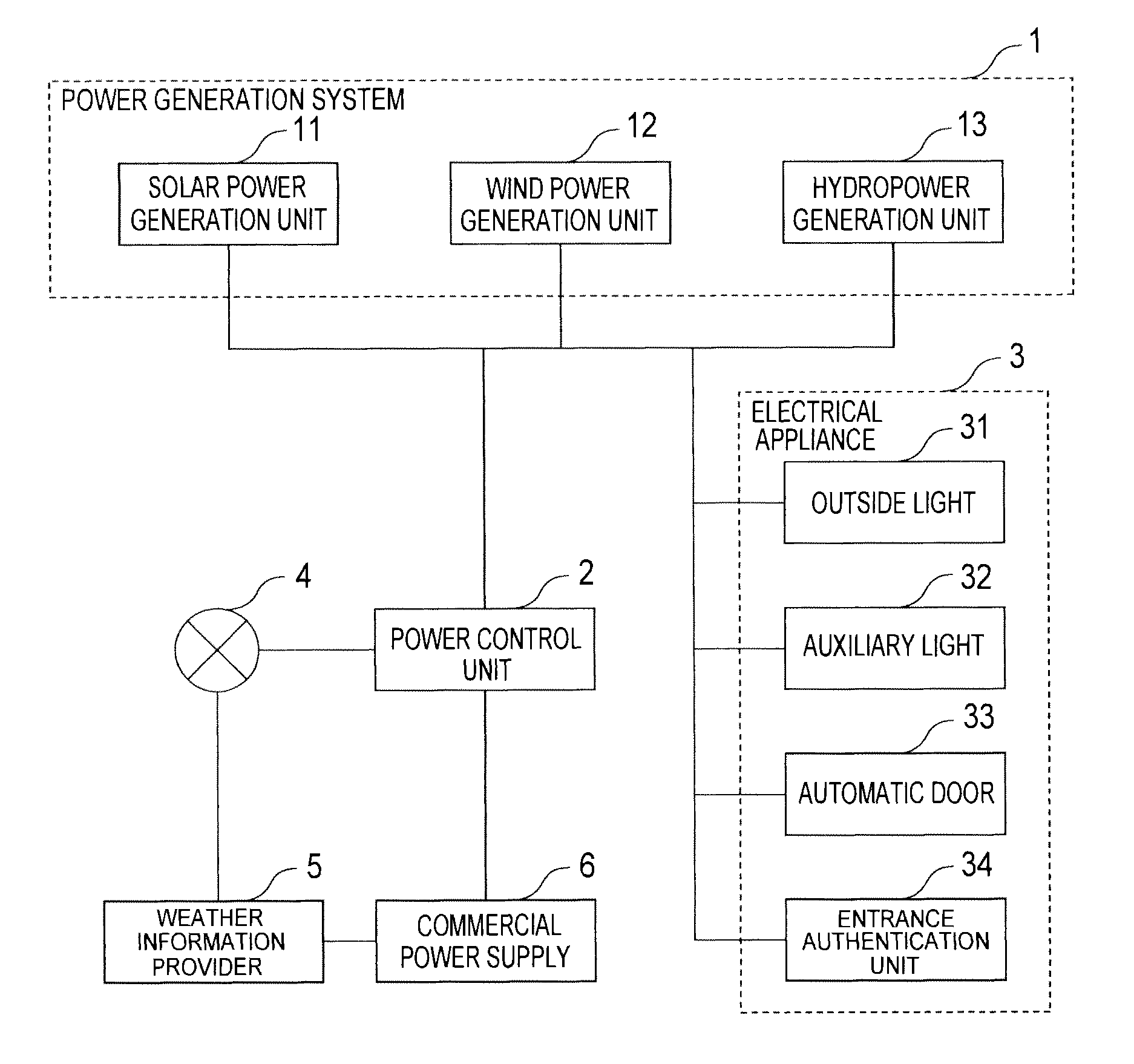
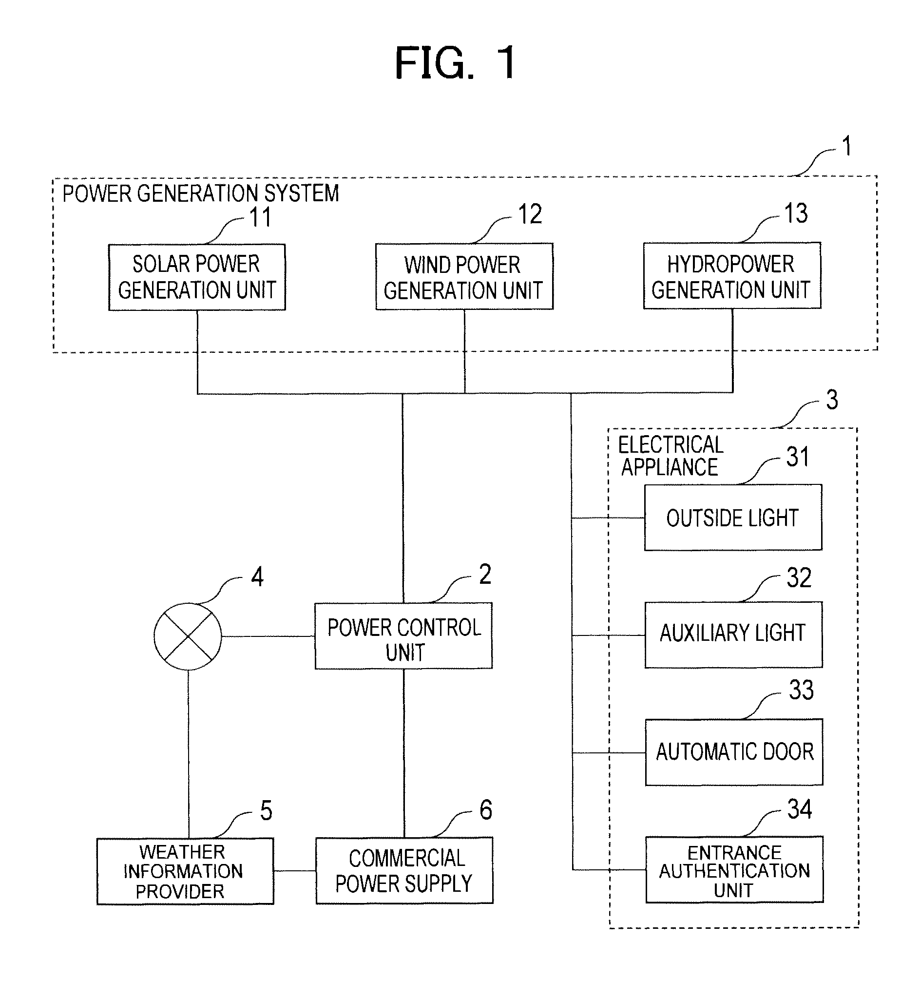
[0028]FIG. 1 is a whole block diagram showing the first embodiment of a power supply system in which a power control unit of the present invention is applied, on the assumption of a commonly used electric equipment inside a building, for example, an apartment or an office building. The system configuration includes a power generation system 1 including a plurality of power generation units, an electrical appliance 3 including a plurality of power consuming appliances, and a power control unit 2 controlling the power generation system 1 and controlling the power supply to the electrical appliance 3. Further, the system has a network 4 for acquiring information from external devices. The system is connected to a weather information provider 5 for acquiring weather information, and is connected also to a commercial power supply 6 given from an electric power company. The power generation system 1, the commercial power supply 6, and the electrical appliance 3 are connected with each oth...
second embodiment
[0071]FIG. 10 is a whole block diagram showing a second embodiment of a power supply system which includes a power control unit of the present invention. In the first embodiment, the electric power generated by the power generation system has been transmitted to the electric appliances, as is. However, in this embodiment, the charging unit 7 is added, and the charging unit 7 is charged with the generated power once. Then, the power is supplied to the electrical appliances 3. Other configurations are the same as those of the first embodiment (FIG. 1). The power control unit 2 controls also the charging unit 7.
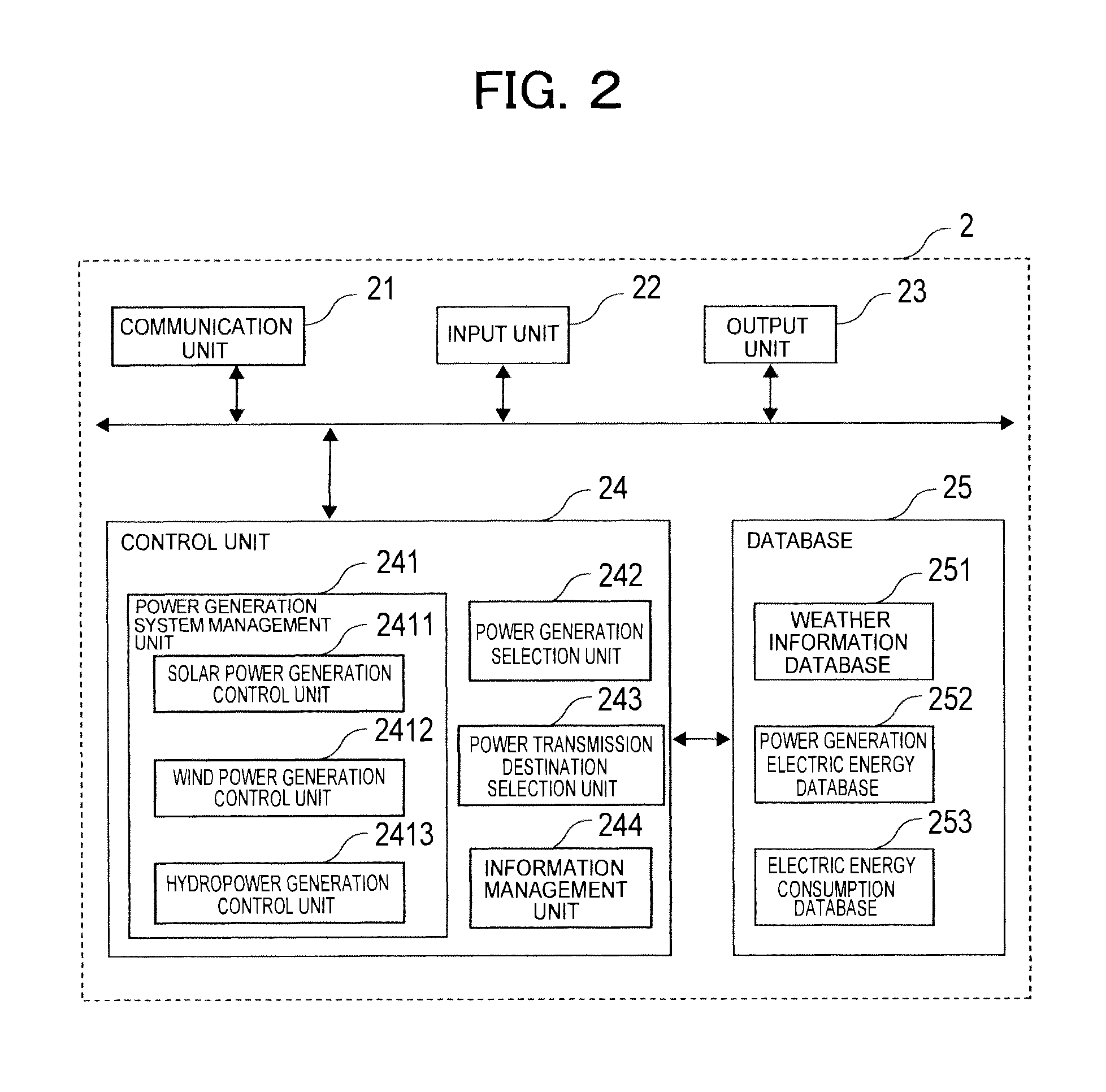
[0072]FIG. 11 is a block diagram showing an example of the power control unit 2. Added in the control unit 24 is a charging unit management unit 245 which controls the charging unit 7. The charging unit management unit 245 acquires information regarding the charging unit 7 through the information management unit 244, and controls the charging operation of the charging unit 7. Ot...
third embodiment
[0079]FIG. 13 is a whole block diagram showing a third embodiment of a power supply system in which the power control unit of the present invention is applied. In the above-described first and second embodiments, the power generation unit adapts a scheme using natural energy. However, this embodiment applies a piezoelectric power generation scheme using the step pressure of the user inside the building, and efficiently applies a power generation method in accordance with the behavioral pattern of the user.
[0080]The system configuration employs a piezoelectric generation unit 14 as the power generation system 1, charges the charging unit 7 with generated electric power from the piezoelectric generation unit 14, and transmits the power to the electrical appliance 3. The connection with the weather information provider 5 as described in the first and second embodiments is not made in this embodiment.
[0081]A plurality of piezoelectric generation units 14 are installed in the building, a...
PUM
 Abstract
Description
Claims
Application Information
 - R&D
- Intellectual Property
- Life Sciences
- Materials
- Tech Scout
- Unparalleled Data Quality
- Higher Quality Content
- 60% Fewer Hallucinations
Browse by: Latest US Patents, China's latest patents, Technical Efficacy Thesaurus, Application Domain, Technology Topic, Popular Technical Reports.
© 2025 PatSnap. All rights reserved.Legal|Privacy policy|Modern Slavery Act Transparency Statement|Sitemap|About US| Contact US: help@patsnap.com