Methods for measuring leakage rate and inferring production rate of an oilfield downhole pump

a technology of leakage rate and production rate, which is applied in the direction of instruments, borehole/well accessories, surveys, etc., can solve the problems of high cost of design and maintaining facilities to separate and measure these mixtures for each well, the production test method described above is far from ideal, and the test metering system is expensive to construct and maintain. , to achieve the effect of improving the accuracy of determining the traveling valve/plunger

Active Publication Date: 2013-01-24
RAVDOS HLDG INC
View PDF4 Cites 36 Cited by
  • Summary
  • Abstract
  • Description
  • Claims
  • Application Information

AI Technical Summary

Benefits of technology

[0054]An object of this invention is to provide improvements in the accuracy of determining traveling valve / plunger leakage rates and inferred production of a downhole pump of an oil and gas well.

Problems solved by technology

Designing and maintaining facilities to separate and measure these mixtures for each well is typically cost-prohibitive.
The production test method described above is far from ideal.
The test metering systems are expensive to construct and to maintain.
Various practical operational factors can cause the individual well “tests” to be inaccurate.
Furthermore, the method does not account for transient events which occur throughout the aggregate metering period (e.g. a month) at individual wells.
Even with such traditional production testing, it may not be feasible to meet regulatory requirements.
The “positive displacement meter” concept, though, is not purely applicable to oilfield downhole pumps.
The k factor accounts for the fact that the assumptions about actual conditions mentioned above are not always correct.
Yet pump metering techniques can only measure volumes at down-hole pump conditions.
First, there is an amount of plunger movement which must occur to counteract tubing contraction.
Any time there is a pressure difference across the plunger, there will be some leakage.
When an estimation of Sleakage is not applied to actual field data, the result is over-estimation of the net pump stroke, because the total offset in position between TVC and SVO exceeds that predicted by the tubing contraction St calculation.
As Chambliss pointed out, attempts to experimentally validate these mathematical models have been troublesome, at best.
Even under laboratory conditions where all of the parameters entered into the model are known, there is still a considerable amount of uncertainty in the results.
Therefore practitioners in the industry cannot rely on any of these models as a means to correct positive displacement pump meters for slip.
Presumably this means pumps with high slippage.
The “Pump card method” has proven difficult to implement even when a human attempts to interpret the data.
Downhole pump cards are the result of a complex chain of calculations derived from raw data which includes a degree of error or noise.
The result is that downhole cards can be “noisy” and tend to have fairly low resolution in time.
As a result, the “standard valve opening” (SVO) time is difficult (sometimes impossible) for even a human to identify.
Logic designed for a controller to interpret this data, almost certainly results in frequent erroneous selection of “standing valve opening” time, thereby yielding incorrect estimates of pump leakage.
Therefore, the Gibbs and Nolen “Pump Card method” does not provide a generally useful method of estimating pump leakage across a broad range of oilfield installations.
This strain is then considered to result in downhole pump plunger movement.
Although the Gibbs and Nolen “Traveling Valve Load Loss Rate” method and variants of the technique have been widely used throughout the industry for many years, no literature can be found which challenges or confirms the validity of the “Traveling Valve Load Loss Rate” procedure.
Gibbs and Nolen did not provide any theoretical basis for assuming a relationship between leakage rate and time.
In all three cases, the second order equation does a very poor job of approximating the entire raw data set.
Such variability in leakage estimates is highly undesirable.
However, operational conditions can easily invalidate the assumption of incompressible fluid.
Problems with fluid compressibility are most serious during the very early parts of the traveling valve leakage test, where the pressure in the barrel is lowest.
Therefore, the fluid compressibility phenomena can introduce significant error into the leakage calculations.

Method used


Image

  • Methods for measuring leakage rate and inferring production rate of an oilfield downhole pump
  • Methods for measuring leakage rate and inferring production rate of an oilfield downhole pump
  • Methods for measuring leakage rate and inferring production rate of an oilfield downhole pump

Examples


Embodiment Construction

[0099]Estimating Leakage Rate from a Traveling Valve Check

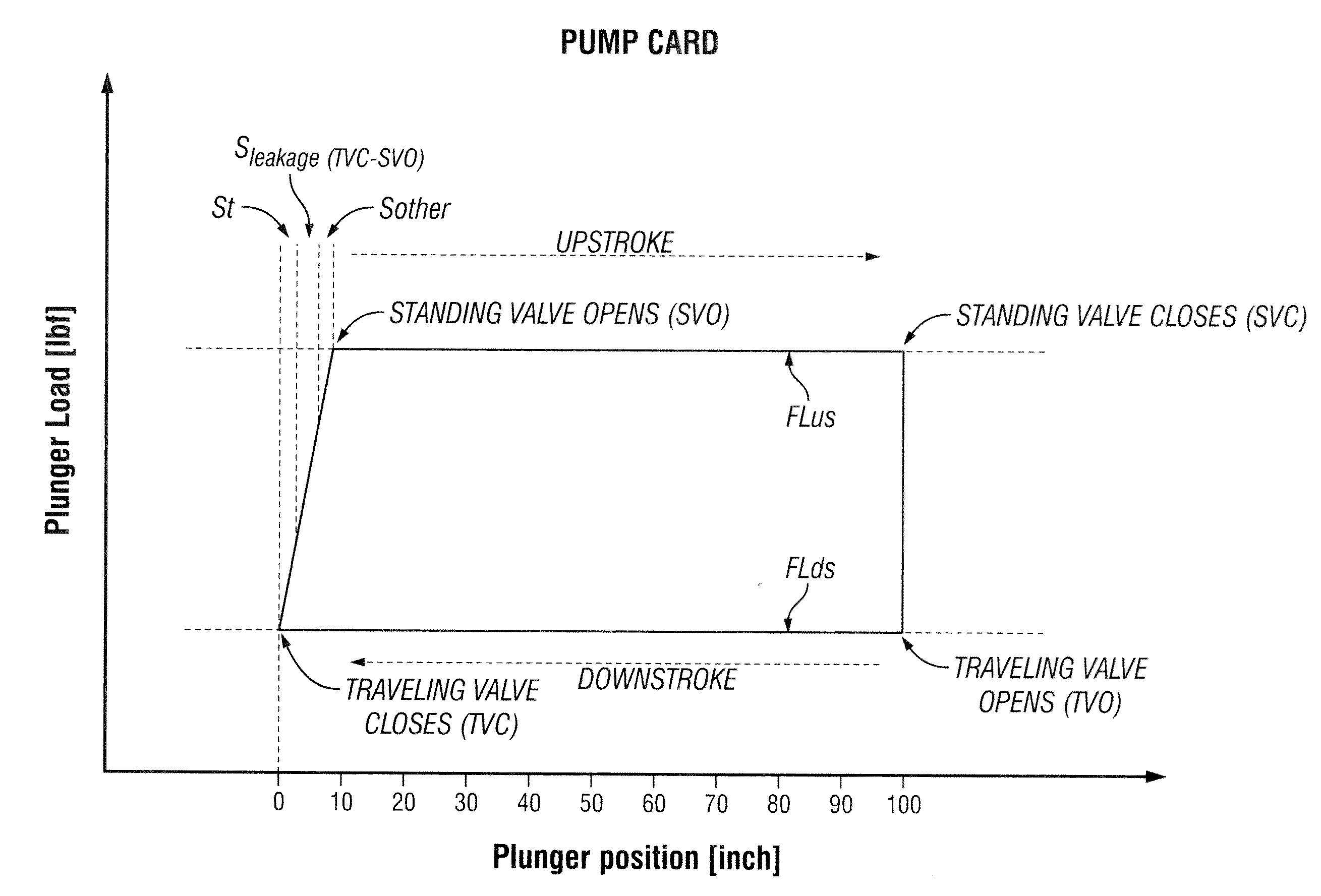
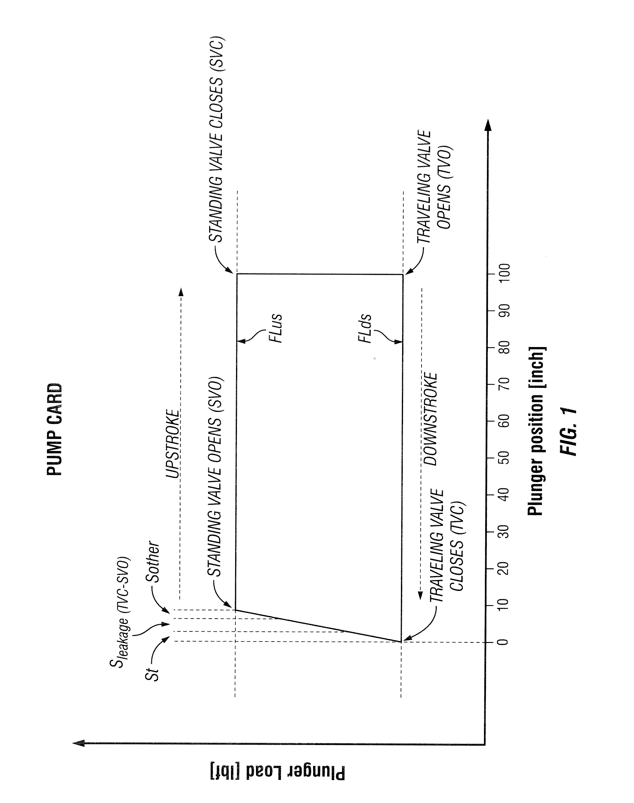
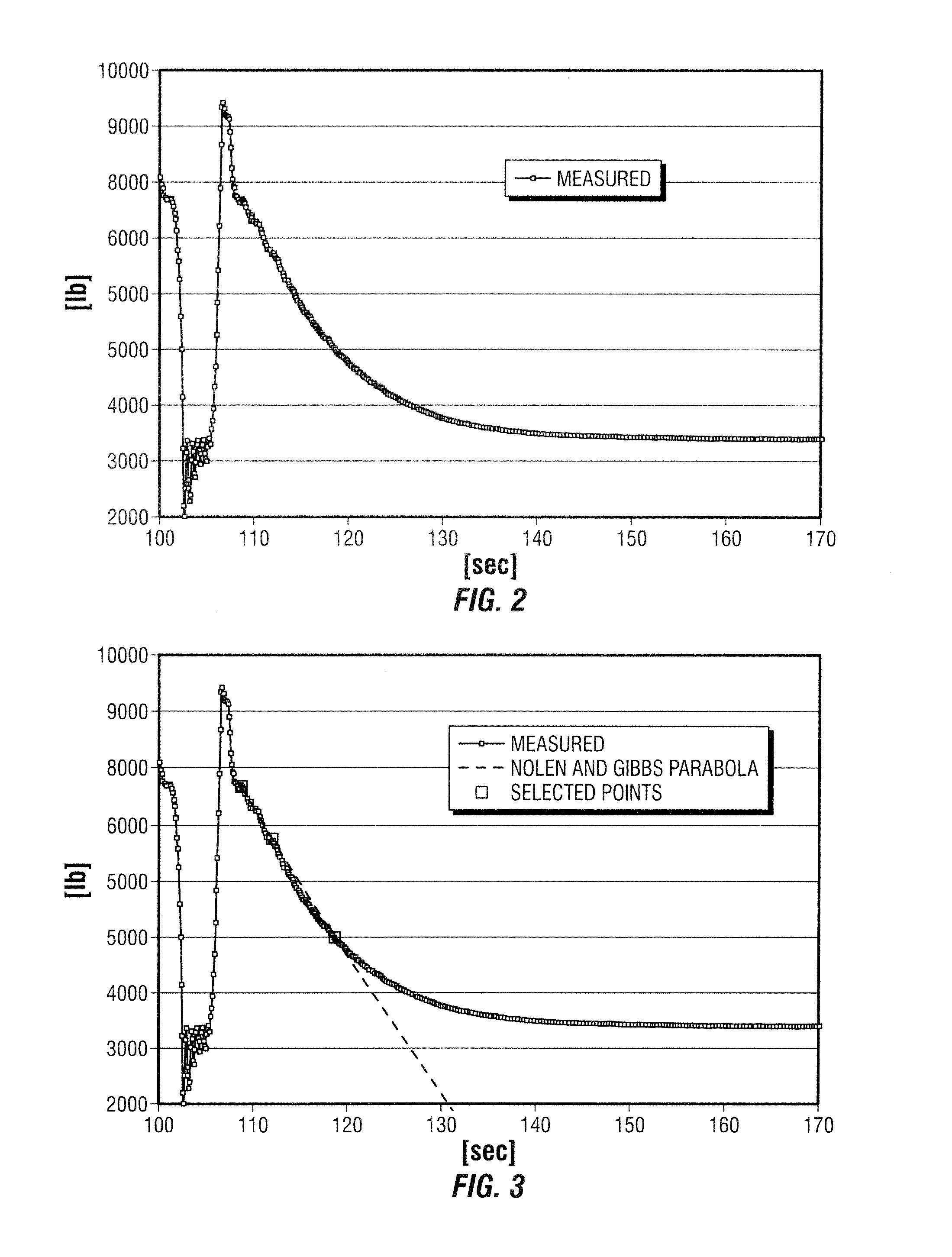
[0100]One aspect of the invention includes a method for interpreting the “traveling valve test”. This test is performed by stopping the pumping unit during the upstroke and measuring load on the polished rod vs time. See the upstroke portion of the pump illustrated in FIG. 1. See also FIGS. 6A and 6B which illustrate a full pump card and plunger positions and plunger loads during a pump cycle.

[0101]See also FIGS. 8A and 8B which illustrate a pump card and plunger movement for a downhole pump with early standing valve closing.

[0102]FIGS. 9A and 9B illustrate a pump card and plunger movement for a downhole pump with incomplete fillage.

[0103]There is general agreement among theoretical investigators that instantaneous plunger traveling valve leakage rate is proportional to pressure differential across the pump, or:

Qleakage=Cx*ΔPplunger  (1)[0104]where,

Qleakage is the instantaneous plunger / traveling valve leakage rate,

ΔPplunger i...


PUM


Abstract

Methods for measuring the leakage rate of a downhole pump using either measured axial load information from the drive rod string or using measured production data. The invention is for methods of applying the leakage rate to a downhole dynamometer card, for a reciprocating rod pump, for determining well production.

Description

BACKGROUND OF THE INVENTION[0001]1. Field of the Invention[0002]This invention is related generally to oilfield equipment for monitoring and controlling wells that are produced by rod pumping where subsurface fluid pumps are driven via a rod string which is reciprocated by a pumping unit located at the surface.[0003]In particular, the invention concerns methods for measuring the leakage rate of the downhole pump using either measured axial load information from the drive rod string or using measured production data. The invention also concerns methods for applying that leakage rate to a downhole dynamometer card (for reciprocating rod pumps) for determining well production.[0004]2. Description of the Prior ArtTraditional Production Testing[0005]Knowledge of fluid production from individual wells is crucial to commercial oil and gas production. At a minimum, such knowledge facilitates accurate royalty payment, proper regulatory reporting, and improved operational decisions.[0006]Howe...

Claims


Application Information

Patent Timeline
Patent Type & Authority Applications(United States)
IPC IPC(8): G06F19/00G16Z99/00
CPCE21B47/0008G01F3/14G06F17/40G06F19/00E21B47/10G16Z99/00E21B47/009
Inventor MILLS, THOMAS M.
Owner RAVDOS HLDG INC
Why Eureka
Try Eureka