Method and Machining Installation for the Finishing of a Crankshaft Bearing Bore

a technology for crankshaft bearings and installation methods, which is applied in the direction of honing tools, reaming devices, manufacturing tools, etc., can solve the problems of high-precision machining

Inactive Publication Date: 2013-01-31
NAGEL MASCHEN UND WERKZEUGFAB +1
View PDF11 Cites 10 Cited by
  • Summary
  • Abstract
  • Description
  • Claims
  • Application Information

AI Technical Summary

Problems solved by technology

The multiplicity of operations are provided because irregularities, for example caused by the casting of the cylinder crankcase, make it necessary for relatively great amounts of material, of se...

Method used


Image

  • Method and Machining Installation for the Finishing of a Crankshaft Bearing Bore
  • Method and Machining Installation for the Finishing of a Crankshaft Bearing Bore
  • Method and Machining Installation for the Finishing of a Crankshaft Bearing Bore

Examples


Embodiment Construction

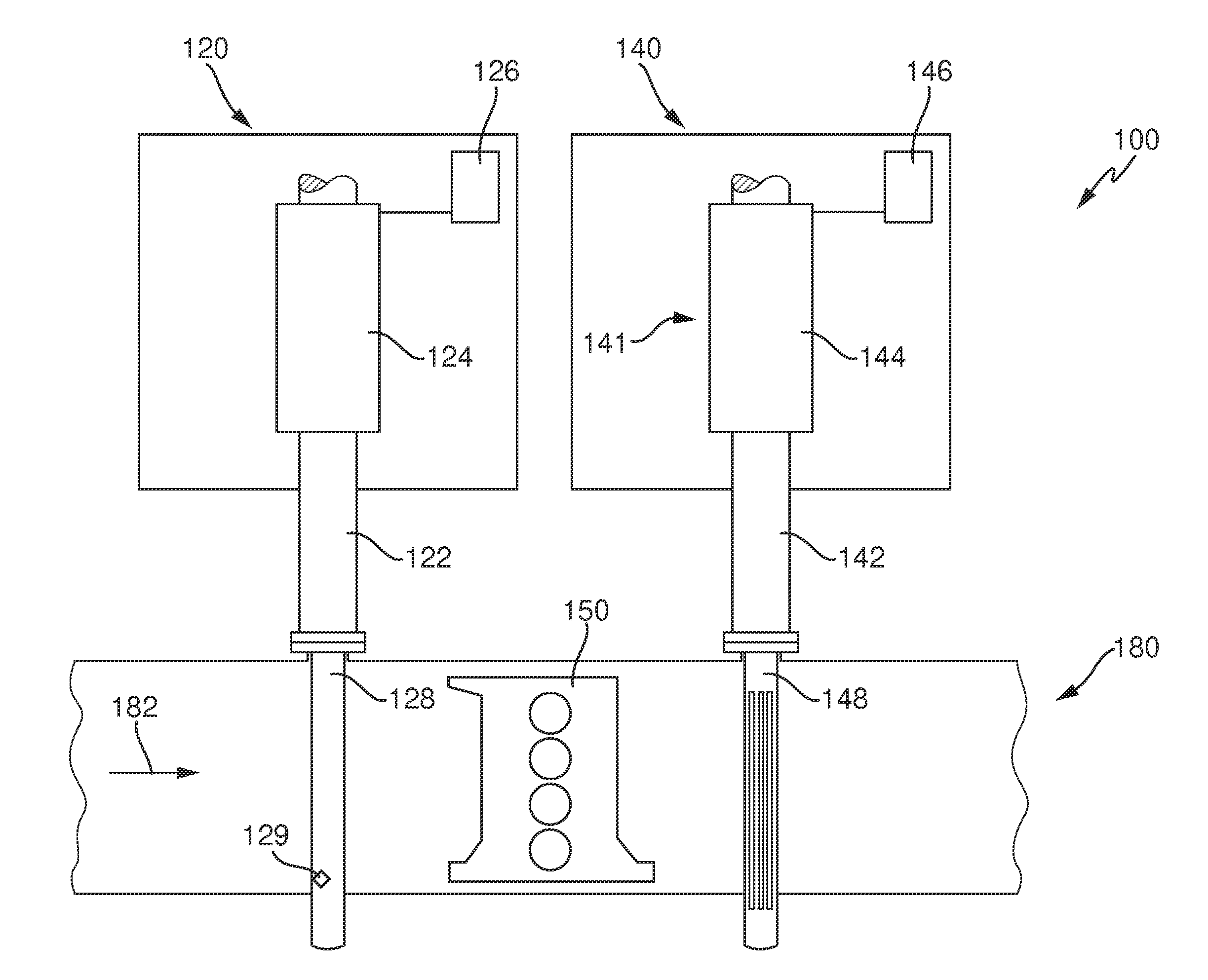
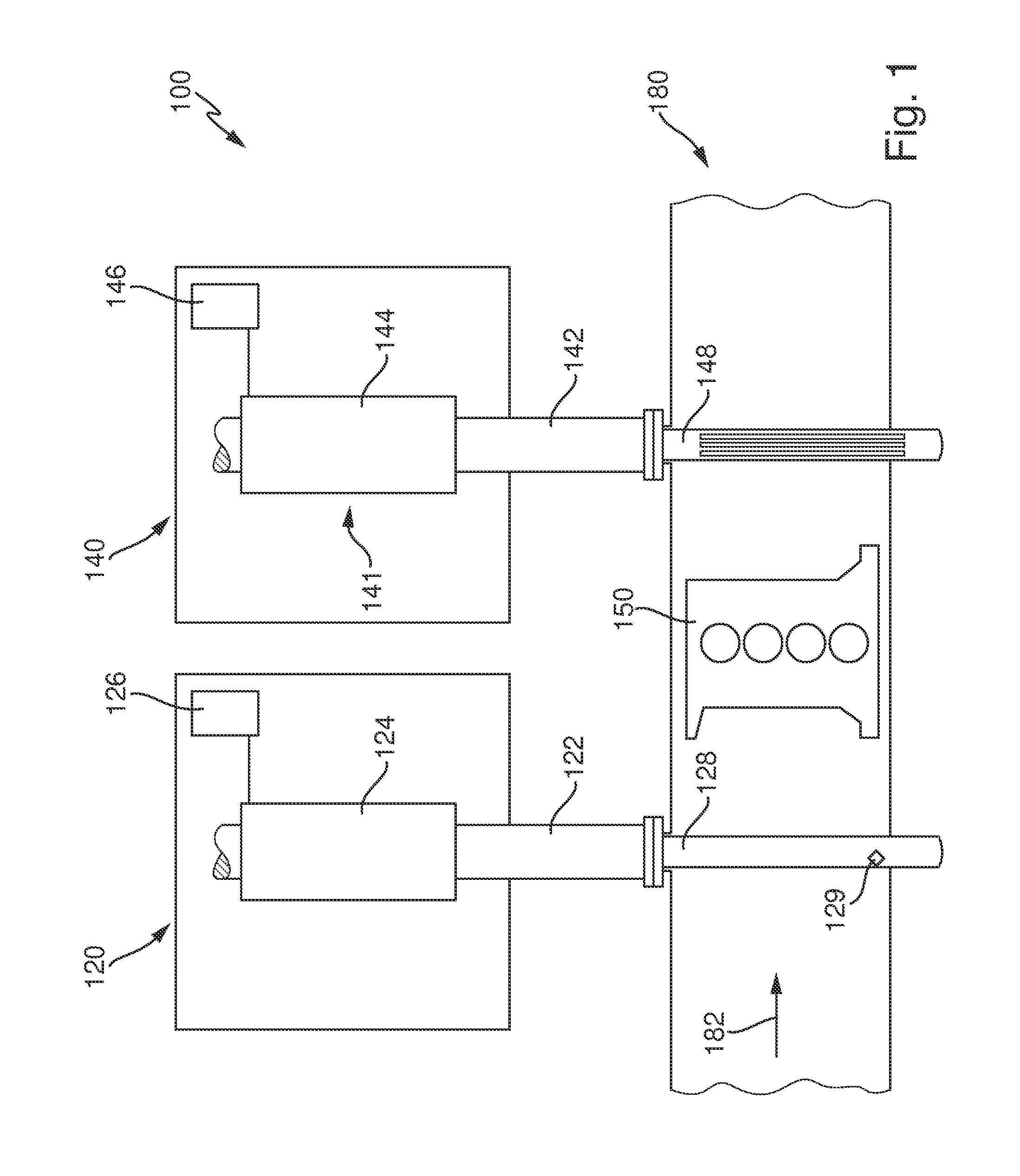
[0075]In FIG. 1 there is shown a schematic plan view of part of an embodiment of a machining installation 100 for the finishing of crankshaft bearing bores in cylinder crankcases of internal combustion engines. The entire machining installation, only part of which is represented here, is designed for complete finishing of the crankshaft bearing bore directly following the assembly of the individual parts of the engine block that form the crankshaft bearing bore.

[0076]In the case of the example, a workpiece 150 to be machined is a cylinder crankcase for an in-line four-cylinder engine. The detail shown of a production line for the complete machining of these workpieces shows a machine tool designed as a precision drilling machine, with a precision drilling device 120 and a honing machine, following in the direction of material flow 182, with a honing device 140. The precision drilling device 120 and the honing device 140 are provided here on separate machine beds, but they may also b...


PUM

PropertyMeasurementUnit
Lengthaaaaaaaaaa
Lengthaaaaaaaaaa
Angleaaaaaaaaaa

Abstract

In a method for the finishing of a crankshaft bearing bore in a cylinder crankcase of an internal combustion engine, starting from a prepared crankshaft bearing bore, a finished crankshaft bearing bore is produced with a prescribable desired size, a prescribable desired structure of the bore inner surface and a prescribable desired position of the bore axis. The prepared crankshaft bearing bore is first finished with at least one finishing tool with a geometrically defined cutting edge and then the honing of the crankshaft bearing bore is carried out. In a final finishing operation with a geometrically defined cutting edge immediately preceding the honing, an allowance of at least 0.4 mm is removed, and the honing tool is introduced into the bore coaxially in relation to the desired position of the bore axis and moved within the bore, an allowance of at least 0.08 mm being removed during the honing.

Description

CROSS-REFERENCE TO RELATED APPLICATIONS[0001]The present application claims priority to German Patent Application No. 10 2011 079 900.1, filed Jul. 27, 2011, the entirety of which is incorporated herein by reference.BACKGROUND AND PRIOR ART[0002]The invention relates to a method for the finishing of a crankshaft bearing bore in a cylinder crankcase of an internal combustion engine. The invention also relates to a machining installation suitable for carrying out the method.[0003]The cylinder crankcase, which is often also referred to simply as the “crankcase” or “engine block”, is an integral part of combustion engines or internal combustion engines, as are used for example in passenger cars or trucks, aircraft, ships or stationary installations. The most widely encountered design is that of multi-cylinder engines, the pistons of which are connected by means of connecting rods to the rotating crankshaft, which passes on the power generated by the engine to wheels, propellers, generat...

Claims


Application Information

Patent Timeline
IPC IPC(8): B23P23/02B24B33/02B23D75/00B23P15/00
CPCB23B41/12B24B33/022Y10T29/49231Y10T29/5176Y10T409/303752Y10T29/4927Y10T408/03B24B33/02B24B33/08
Inventor NAGEL, BERNDMAYER, MARTINWANKMILLER, GERMANWASSERMANN, GEORG
Owner NAGEL MASCHEN UND WERKZEUGFAB
Why Eureka
Try Eureka