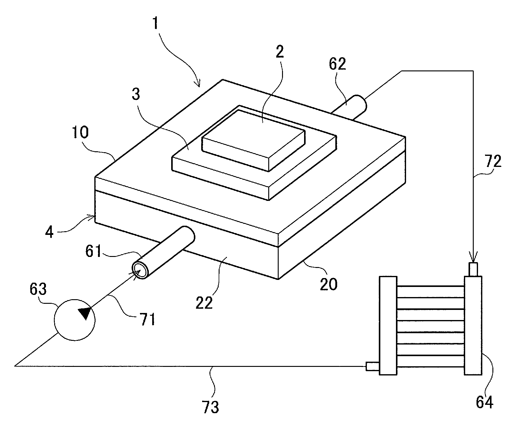
Cooler

a cooling device and cooling fin technology, applied in the field of cooling devices, can solve the problems of increasing the amount of heat generated by semiconductor devices, and achieve the effects of enhancing cooling performance, preventing stagnation of coolant near the lowered curved portion, and improving the heat transfer coefficient of the wavy fins

Inactive Publication Date: 2013-01-31
TOYOTA JIDOSHA KK
View PDF5 Cites 12 Cited by
  • Summary
  • Abstract
  • Description
  • Claims
  • Application Information

AI Technical Summary

Benefits of technology

[0012]The advantageous effects of the cooler will be described.
[0013]With the configuration (1), the stagnation preventing member creates a flow of coolant from the raised curved portion toward an opposite lowered curved portion. Thereby, the main stream of the coolant that tends to flow straight can be mixed with the coolant stagnating near the lowered curved portion, whereby the heat transfer coefficient of the wavy fins can be improved. Thus, stagnation of the coolant near the lowered curved portion can be prevented, so that the cooler can have enhanced cooling performance.
[0014]With the configuration (2), there is created a flow of the coolant from the base portion of the raised curved portion on the semiconductor device side toward the opposite lowered curved portion. Thereby, the coolant is disturbed near the base portions of the wavy fins where the temperature is relatively high. Therefore, the heat transfer coefficient of the wavy fins can be effectively improved. Moreover, by providing the stagnation preventing member only at the base portion, pressure fluctuations of the coolant caused by the stagnation preventing member can be reduced and pressure loss increase of the cooler can be kept small.
[0015]With the configuration (3), the tapered bank creates a flow of the coolant from the bank toward the bottom wall of the cooling case in addition to the flow of coolant from the bank toward the lowered curved portion. Therefore, the coolant can be disturbed largely near the bank, so that the heat exchange rate of the wavy fins can be effectively improved.
[0016]With the configuration (4), the stagnation preventing member is a protrusion, i.e., the stagnation preventing member can be provided with a very simple configuration. The protrusion can be configured small, so that pressure fluctuations of the coolant caused by the protrusion are reduced, and there will be almost no increase in the pressure loss in the cooler.
[0017]With the configuration (5), the stagnation preventing member and the second stagnation preventing member create flow of the coolant from the raised curved portion toward the opposite lowered curved portion. Thereby, the main stream of the coolant that tends to flow straight can be mixed substantially with the coolant stagnating near the lowered curved portion, whereby the heat transfer coefficient of the wavy fins can be largely improved.

Problems solved by technology

The amount of heat the semiconductor device generates has been increasing since such an inverter device is required to be small and lightweight and yet to provide high power output.

Method used


Image

  • Cooler
  • Cooler
  • Cooler

Examples


first embodiment

[0069]The advantageous effects of the cooler 4 of the first embodiment will be described. In this cooler 4, as shown in FIG. 9, the banks 31x create flows of the coolant 40 from the raised curved portions 31 toward the opposite lowered curved portions 32. Thereby, the part MS1 of the main stream MS of the coolant 40 can be mixed with the coolant 40 stagnating near the lowered curved portions 32, whereby the heat transfer coefficient of the wavy fins 30 can be improved. Thus, stagnation of the coolant 40 near the lowered curved portions 32 can be prevented, so that the cooler 4 can have enhanced cooling performance.

[0070]In the cooler 4 of the first embodiment, as shown in FIG. 7, the banks 31x provided at the base portions 31a create flows of coolant from the base portions 31a of the raised curved portions 31 toward the opposite lowered curved portions 32. Thereby, the coolant 40 is disturbed near the base portions 31a of the wavy fins 30 where the temperature is relatively high. Th...

second embodiment

[0094]In the second embodiment, one protrusion 31y is provided on each raised curved portion 31. Alternately, a plurality of protrusions 31y may be provided on each raised curved portion 31. For example, two protrusions 31y may be provided at the base portion 31a of the raised curved portion 31. Alternatively, one protrusion 31y may be provided at the base portion 31a of the raised curved portion 31, and another protrusion 31y may be provided at the distal portion 31b of the raised curved portion 31. The shape and the size of the protrusions 31y can be changed as required.

third embodiment

[0095]In the third embodiment, the banks 31x are provided at the base portions 31a of the raised curved portions 31, while the second banks 21x are provided at the distal portions 31b of the raised curved portions 31. Alternately, protrusions may be provided at the base portions 31a of the raised curved portions 31 instead of the banks 31x. Alternatively, protrusions may be provided at the distal portions 31b of the raised curved portions 31 instead of the second banks 21x.

[0096]In the forth embodiment, the second banks 90x are provided on the sheet member 90. Alternately, protrusions may be provided on the sheet member 90.

[0097]In each embodiment mentioned above, the distance (flow path width) of the adjacent wavy fins 30 is made constant at any points in the flowing direction, but it may be changed at any points in the flowing direction.


PUM


Abstract

A cooler includes a plate, a cooling case having a coolant flowing therein, and a plurality of wavy fins having a raised curved portion and a lowered curved portion formed alternately on a side face in a flow direction of the coolant. In this cooler, the coolant flows through between the raised curved portion and the lowered curved portion opposite to each other in a meandering manner. The raised curved portion is provided with a bank creating a flow of coolant from the raised curved portion toward the opposite lowered curved portion. With this bank, a part of a main stream of the coolant can be mixed with the coolant stagnating near the lowered curved portion, whereby the heat transfer coefficient of the wavy fins can be improved. Thus, stagnation of the coolant near the lowered curved portion can be prevented, so that the cooler can have enhanced cooling performance.

Description

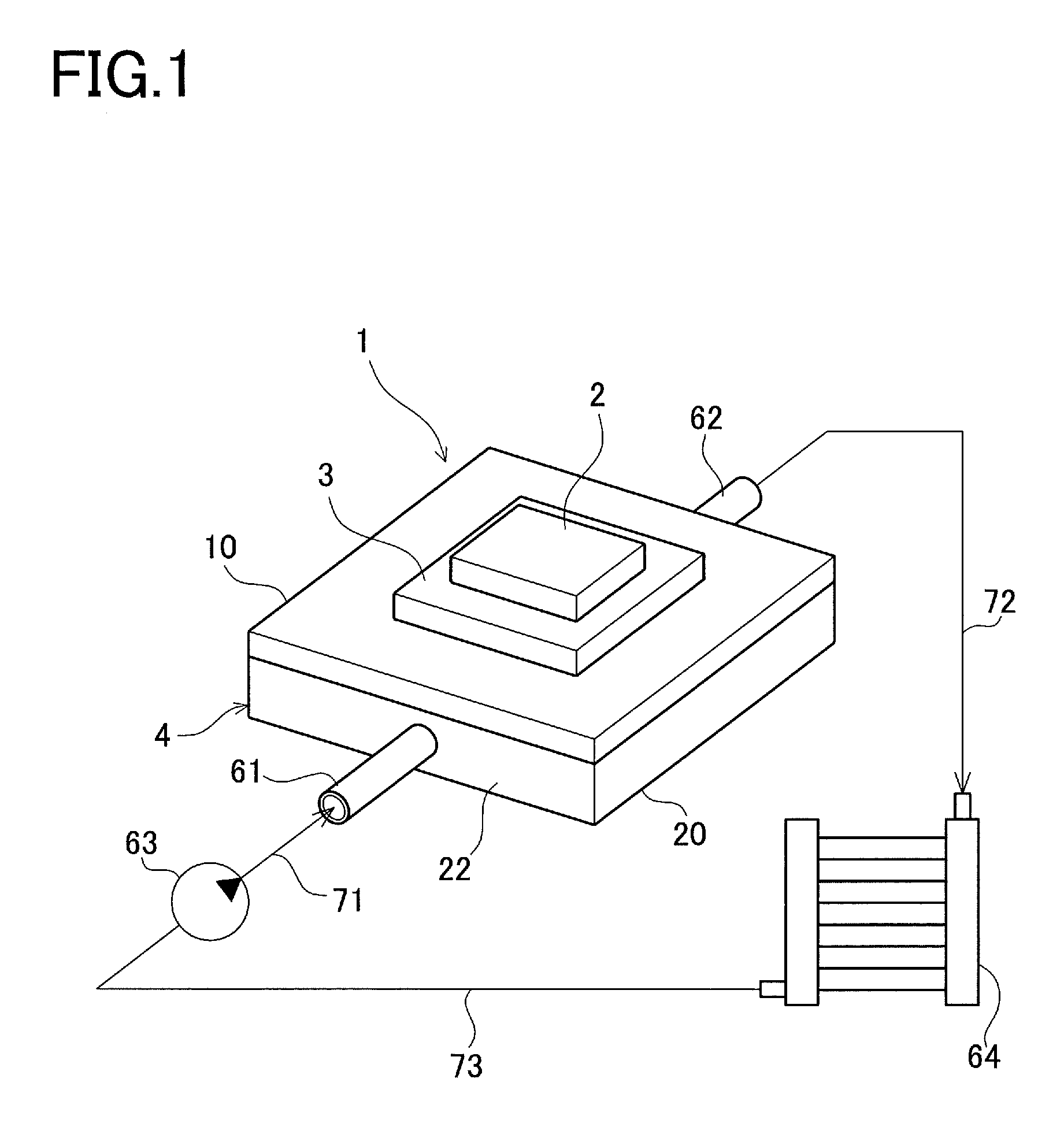
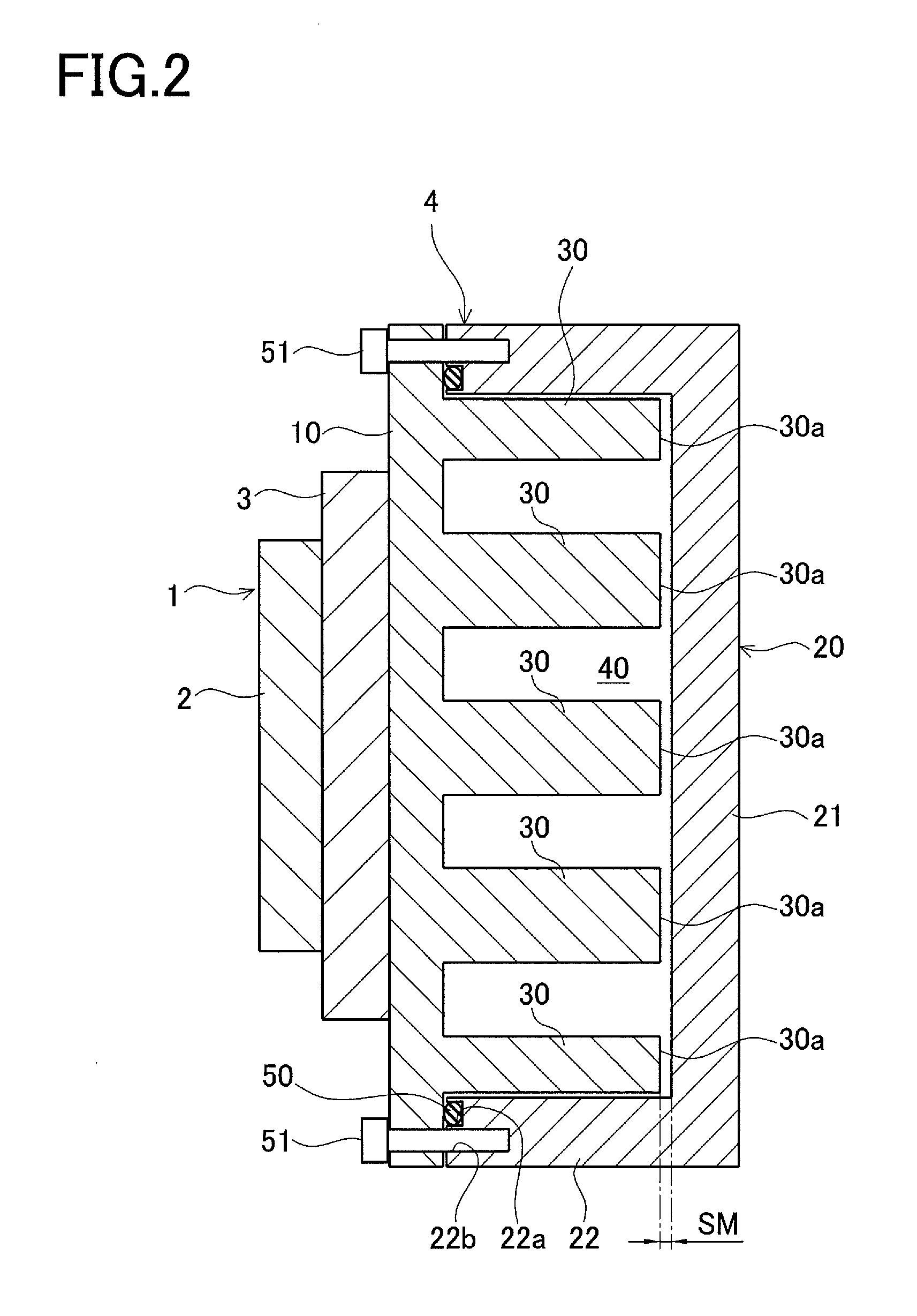
TECHNICAL FIELD[0001]The present invention relates to a cooler in which a coolant flows along wavy fins arranged between a plate and a cooling case, and more particularly to a cooler with improved cooling performance.BACKGROUND ART[0002]In hybrid electric vehicles or the like, an inverter device (power conversion device) performs power conversion. The inverter device having a semiconductor device mounted therein is equipped with a cooler for cooling the heat generated by switching the semiconductor device. The amount of heat the semiconductor device generates has been increasing since such an inverter device is required to be small and lightweight and yet to provide high power output. Accordingly, a cooler with improved cooling performance (heat transfer coefficient) to keep stable operation of the inverter device is being sought after.[0003]Patent Literature 1 specified below, for example, describes a cooler with improved cooling performance. The cooler described in Patent Literatu...

Claims


Application Information

Patent Timeline
Patent Type & Authority Applications(United States)
IPC IPC(8): F28F3/02F28F3/12
CPCH01L23/473H01L2924/0002H01L2924/00H01L23/36H05K7/20
Inventor TAKENAGA, TOMOHIRO
Owner TOYOTA JIDOSHA KK
Why Eureka
Try Eureka