
Method for controlling aerogenerators for producing electrical energy

Inactive Publication Date: 2013-01-31
EN ECO SPA
View PDF4 Cites 4 Cited by
  • Summary
  • Abstract
  • Description
  • Claims
  • Application Information

AI Technical Summary

Benefits of technology

The invention aims to improve the control of aerogenerators by using machine learning based on weather conditions. The method can also make better use of limited wind intensity, resulting in higher energy efficiency.

Problems solved by technology

The former are more common but, although their main advantage is that they can start more easily at low wind speeds, they require a directional system to direct the propeller correctly relative to the direction of the wind, and in some cases they are excessively noisy.
In effect, in the specific case of low-power turbines, there are inherent drawbacks which reduce the efficiency of the conversion of kinetic wind energy to electrical energy.
A first drawback is due to the minimum wind speed necessary to overcome the inertia from a stationary condition and to start the turbine (v>3 m / s).
Consequently, the energy potentially available for wind regimes under this threshold is not generally exploited until after a certain transient has elapsed, which may even be very extended in time.
Another drawback is the low efficiency of the turbine in turbulent wind regimes, which can be attributed to the dynamic behaviour of the rotor, that is, to the duration of the transients necessary to bring the rotor to nominal rotation conditions during rapid changes in the wind regime.
Such transients may last many seconds and, in turbulent or variable wind regimes, this inertia once again translates as a significant loss of energy produced.
These factors, added to others which have not been mentioned, lead to substantial differences between actual and theoretical power output, thus increasing the cost of energy production.

Method used


Image

  • Method for controlling aerogenerators for producing electrical energy
  • Method for controlling aerogenerators for producing electrical energy
  • Method for controlling aerogenerators for producing electrical energy

Examples


Embodiment Construction

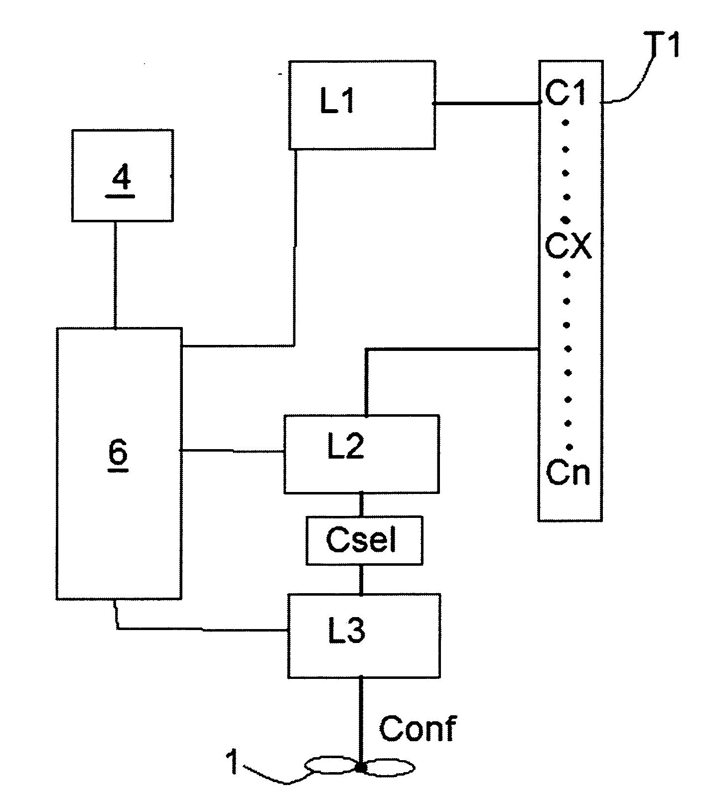
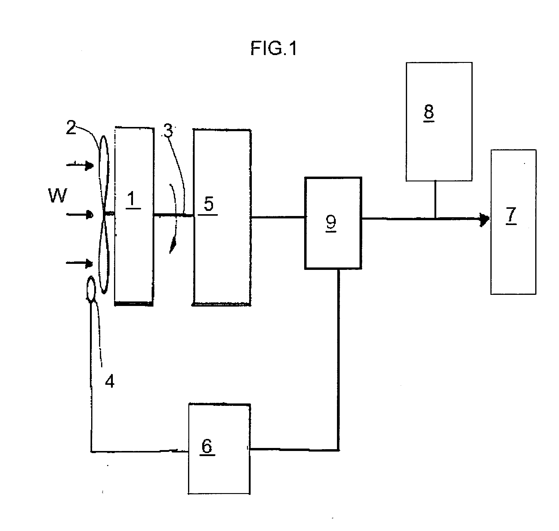
[0024]Described with reference to the accompanying drawings is a method for controlling an aerogenerator 1 for producing electrical energy comprising aerodynamic elements 2 which can rotate about a common vertical or horizontal axis shaft 3 for transmitting a mechanical torque to an alternator unit 5 when the elements 2 are struck by a wind flow W, and consequently generating electrical energy which will be used, through an inverter 9, to power a use point 7 and / or a battery unit 8.

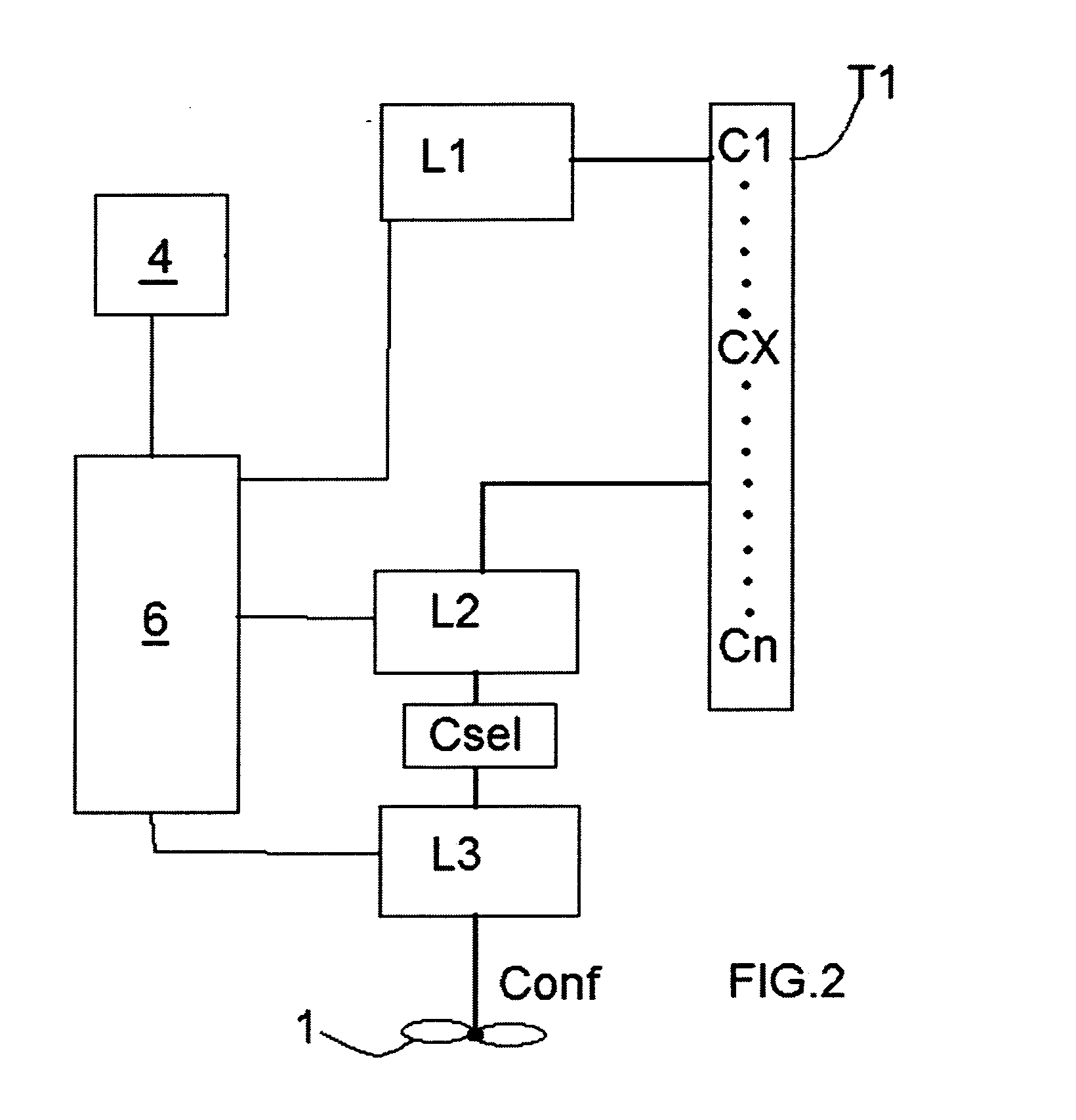
[0025]The alternator 5 is also controlled by a control unit 6 capable of varying the electrical load applied to the alternator and also driving the alternator as a motor, that is, converting the energy accumulated in the battery 8 (or in capacitors set up for the purpose) into a mechanical torque transmitted to the elements 2 through the shaft 3.

[0026]The electrical circuit for the conversion, transmission and accumulation of the energy produced does not per se form the subject-matter of this invention an...


PUM


Abstract

A method for controlling an aerogenerator (1) for producing electrical energy of the type comprising an arrangement of aerodynamic elements (2) that rotate on a common shaft (3), sensors (4) for measuring at least the speed of the wind incident upon said elements (2), an alternator unit (5) associated with the rotation of the shaft (3) for generating electrical energy supplied to a use point (7) and / or to a battery (8) or for transmitting a mechanical torque to the shaft (3), and a control unit (6) associated with the sensor (4) and with the alternator (5) in order to control the alternator (5).

Description

TECHNICAL FIELD[0001]This invention addresses the sector of aerogenerators or wind turbines for producing electrical energy.[0002]Preferably, the invention applies to aerogenerators belonging to the class of small, variable-speed turbines, that is to say, with reference to a classification based on the IEC certification requirements which define a small turbine (SWT—Small Wind Turbine) a wind turbine having a swept surface area smaller than 200 m2, with power ratings from 0 to approximately 100 kW.Prior Art[0003]Up to the present, this range of power ratings includes very different technologies, unlike the sector of megawatt turbines, where the technological solutions are relatively well-established and optimized.[0004]Small aerogenerators differ according to the configuration of the turbine, which may be of the vertical or horizontal axis type, the number of blades, the type of control, the electromechanical power unit and the materials used. Small wind turbines are generally class...

Claims


Application Information

Patent Timeline
IPC IPC(8): H02P9/04
CPCF03D7/046F05B2260/8211Y02E10/723F05B2270/32G05B13/026F05B2270/304Y02E10/72
Inventor MORETTI, GIORGIO
Owner EN ECO SPA
Learn More