Receivers for COFDM digital television transmissions

a digital television and transmission technology, applied in the field of cofdm digital television transmission receivers, stationary and m/h receivers, can solve the problems of low confidence level, low technique, and inability to generate flags for identifying code symbols to be erased, etc., and achieve the highest lack of confidence level

Inactive Publication Date: 2013-01-31
LIMBERG ALLEN LEROY
View PDF0 Cites 38 Cited by
  • Summary
  • Abstract
  • Description
  • Claims
  • Application Information

AI Technical Summary

Benefits of technology

[0017]A receiver of digital signals which embodies the invention includes an inner decoder for iterative soft-decision decoding of turbo coding and an outer decoder for Reed-Solomon coding, output symbols from which inner decoder are rearranged for application to said outer decoder as input symbols thereto. An aspect of the invention is a method of generating flags for identifying code symbols to be erased before the output symbols from the inner decoder are de-interleaved and supplied to the outer decoder for RS coding, which method is novel in that the generation of those flags depends primarily on soft decoding results from the inner decoder. More particularly,

Problems solved by technology

Decoding of the convolutional coding is effective in overcoming corruption caused by Johnson noise, which has additive White Gaussian noise (AWGN) characteristics, but occasionally decoding generates a running error.
In practice, the technique is not very useful until enough corrected RS codewords are available in close parallel disposition with each other to provide a fairly continuous data bitstream, which can then be recoded to CCC for updating previous CCC to generate CCC for the next stage of the CCC decoding and subsequent decoding of the RS coding to be performed.
This second method of generating flags for identifying code symbols to be erased is inferior to the preferred first method that U.S. Pat. No. 5,708,665 describes, in that the error-correction capability of the inner decoder is not taken into account.
Furthermore, the latent delay of the turbo decoder is subject to variati

Method used


Image

  • Receivers for COFDM digital television transmissions
  • Receivers for COFDM digital television transmissions
  • Receivers for COFDM digital television transmissions

Examples


Embodiment Construction

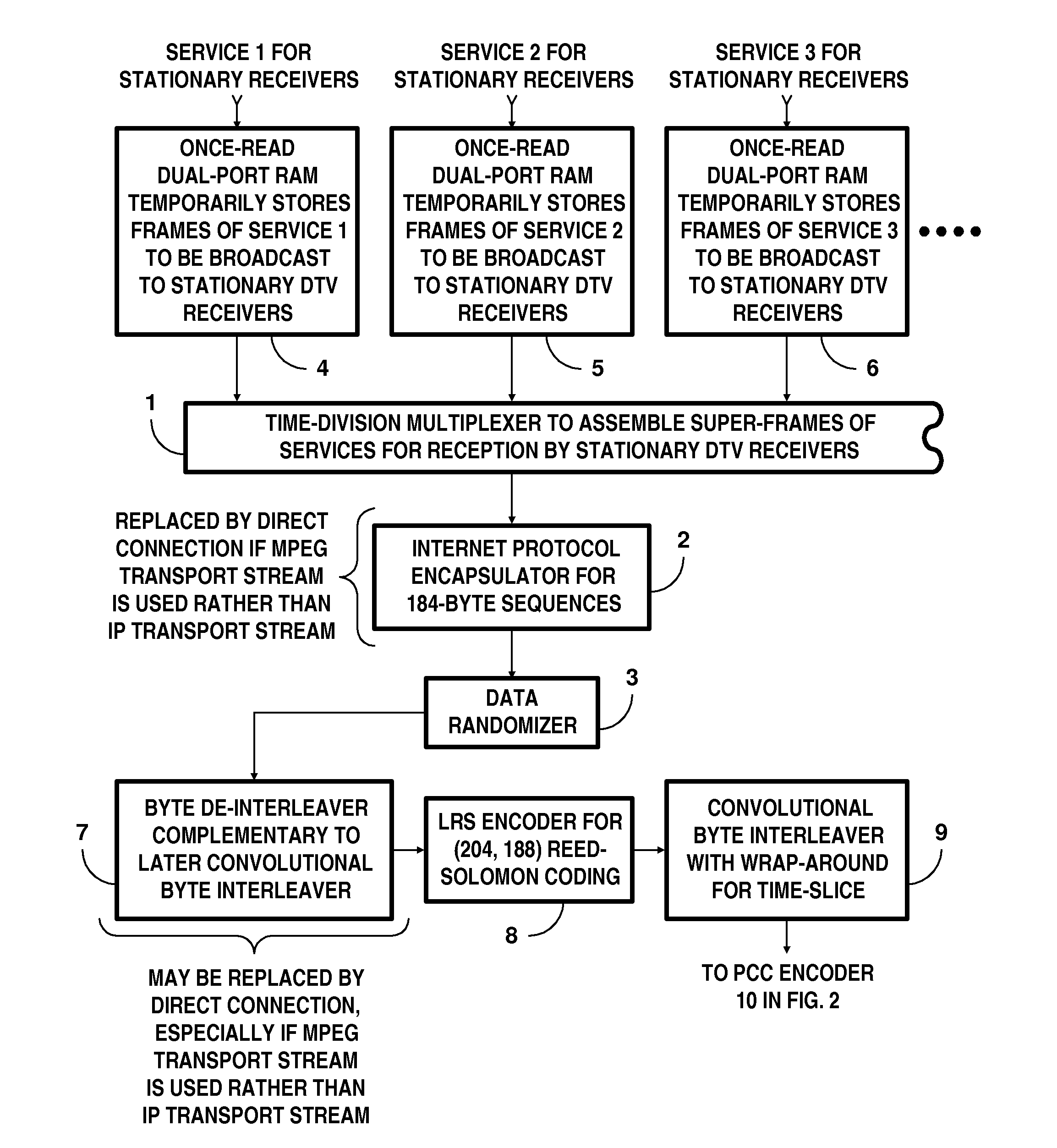
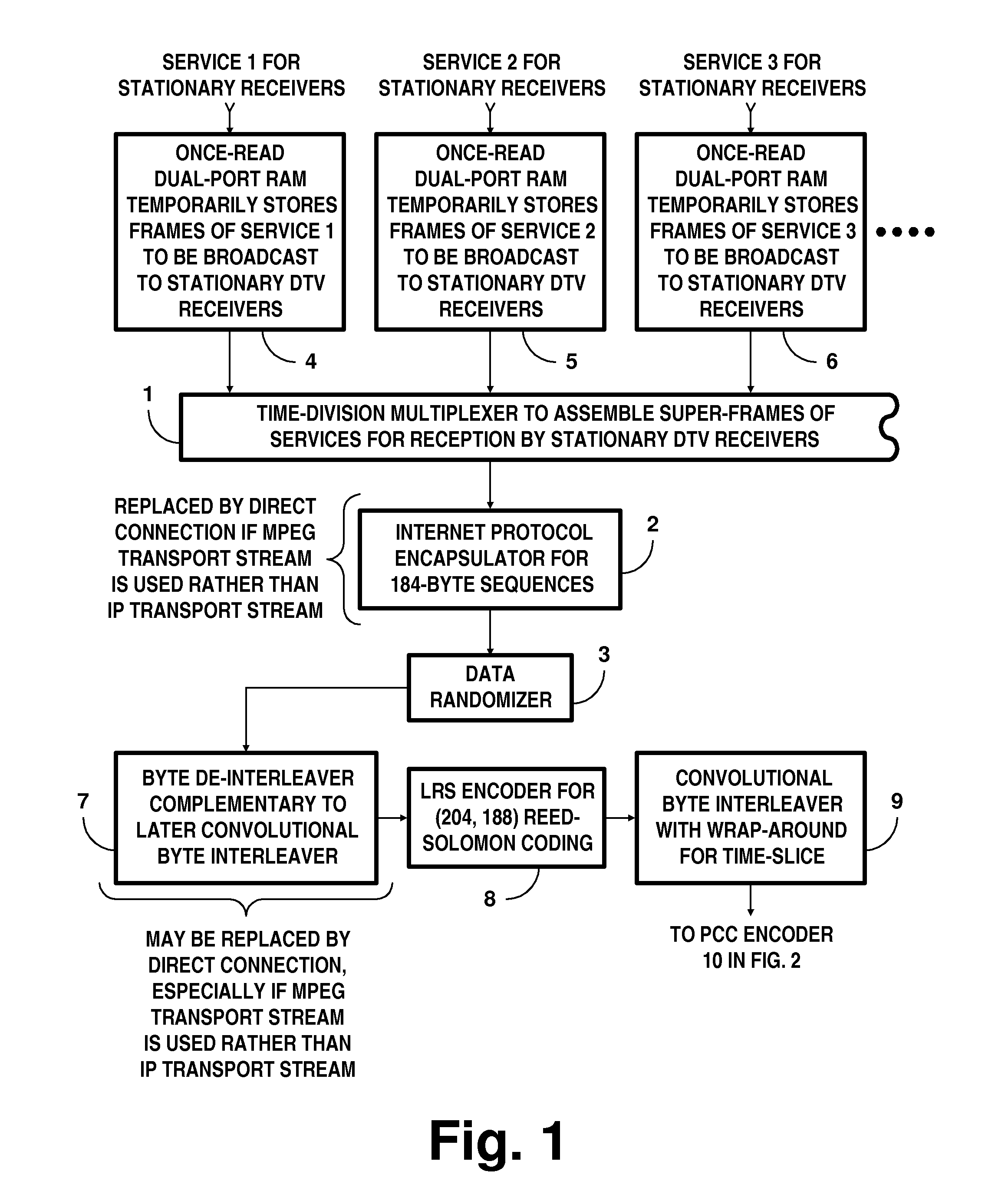
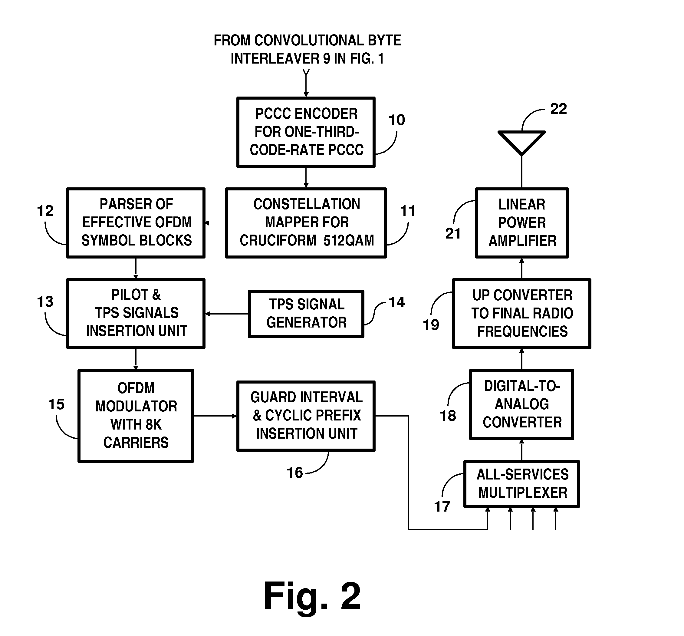
[0052]FIGS. 1 and 2 together show a portion of a DTV transmitter generating COFDM signals for reception by stationary DTV receivers. Apparatus for generating parallel concatenated convolutional coding (PCCC) and subsequent COFDM signals is shown in FIG. 2. FIG. 1 depicts apparatus for processing frames of services to be broadcast to stationary DTV receivers.

[0053]A time-division multiplexer 1 for interleaving time-slices of services to be broadcast to stationary DTV receivers is depicted near the middle of FIG. 1. The time-division multiplexer 1 successively selects time-slices of these various services to be reproduced in its response, which is supplied from its output port.

[0054]FIG. 1 shows the output port of the multiplexer 1 connected to the input port of an internet protocol encapsulator 2, the output port of which IPE 2 connects to the input port of a data randomizer 3.

[0055]The internet protocol encapsulator 2 is used only if the services for reception by stationary DTV rece...


PUM


Abstract

A receiver of COFDM digital television signals includes an inner decoder for iterative soft-decision decoding of concatenated convolutional coding (CCC) and an outer decoder for Reed-Solomon (RS) coding. The receiver generates error flags for identifying code symbols to be erased before the output symbols from the inner decoder are byte de-interleaved and supplied to the outer decoder. Generation of those flags depends on soft decoding results from the inner decoder. The method of locating errors ascribes to each byte supplied to the outer decoder for RS coding the highest lack-of-confidence level specified by the soft data bits associated with that byte. The method is described as being extended to locate byte errors in plural-dimension cross-interleaved Reed-Solomon codes (CIRC) apt to be employed in DTV broadcasting to mobile and handheld receivers.

Description

[0001]This application claims the benefit of the filing dates of provisional U.S. Pat. App. Ser. No. 61 / 574,138 filed 28 Jul. 2011, of provisional U.S. Pat. App. Ser. No. 61 / 574,640 filed 6 Aug. 2011, of provisional U.S. Pat. App. Ser. No. 61 / 626,437 filed 27 Sep. 2011, of provisional U.S. Pat. App. Ser. No. 61 / 627,495 filed 13 Oct. 2011, of provisional U.S. Pat. App. Ser. No. 61 / 628,832 filed 7 Nov. 2011 and of provisional U.S. Pat. App. Ser. No. 61 / 687,516 filed 26 Apr. 2012.FIELD OF THE INVENTION[0002]In general the invention relates to systems of over-the-air broadcasting of digital television (DTV) signals suited for reception by mobile and handset receivers commonly referred to collectively as “M / H” receivers and by “stationary” receivers that customarily remain at one reception site. Each system employs forward-error-correction (FEC) coding of the DTV signals, which are subsequently transmitted using coded orthogonal frequency-division multiplexing (COFDM) of a plurality of c...

Claims


Application Information

Patent Timeline
IPC IPC(8): H04N7/26
CPCH04N21/2383H04N21/41407H04N21/4382H04N21/64322H03M13/09H03M13/1515H03M13/31H03M13/2732H03M13/2918H03M13/2921H03M13/2957H03M13/2966H03M13/2972H03M13/27
Inventor LIMBERG, ALLEN LEROY
Owner LIMBERG ALLEN LEROY
Why Eureka
Try Eureka