Vacuum insulation panel

a vacuum insulation and panel technology, applied in heat-proofing, transportation and packaging, mechanical equipment, etc., can solve the problems of reducing the insulation performance of the panel, and reducing the insulation performance of the conventional vacuum insulation panel, etc., to achieve the effect of preventing deformation, preventing deformation, and preventing deformation

Inactive Publication Date: 2013-01-31
XL CO LTD
View PDF3 Cites 27 Cited by
  • Summary
  • Abstract
  • Description
  • Claims
  • Application Information

AI Technical Summary

Benefits of technology

[0038]To achieve the objects, one aspect of the present invention provides a vacuum insulation panel comprising an outer upper plate, an outer lower plate bonded with the outer upper plate at the edges thereof, a vacuum space defined between the outer upper and lower plates, a spacer provided within the vacuum space for preventing deformation of the outer upper and lower plates by external force, and a getter portion disposed on the inner surface of the outer upper plate.
[0039]Another aspect of the present invention provides a vacuum insulation panel comprising an outer upper plate, an inner plate a side of which is bonded with the outer upper plate at the edges thereof, an upper vacuum space defined between the outer upper plate and the inner plate, an upper spacer provided within the upper vacuum space for preventing deformation of the outer upper plate by external force, an upper getter portion disposed on the inner surface of the outer upper plate, an outer lower plate bei

Problems solved by technology

These materials, however, have disadvantages that they may cause environmental harm after use and they may reduce insulation performance of the panels due to increased pressure by the gas produced by the materials.
The conventional vacuum insulation panels, however, are expensive, heavy, limited in size (30 cm×30 cm), and show low insulation performance at joints of panels.
Even when micropores and cracks are formed on the films, external gas cannot be introduced and the degree of vacuum is not lowered.
The above-described prior art still has problems, however.
The fillers can limit the insulation function.
Accordingly, in case of u

Method used


Image

  • Vacuum insulation panel
  • Vacuum insulation panel
  • Vacuum insulation panel

Examples


examples

[0075]The following examples illustrate the invention and are not intended to limit the same.

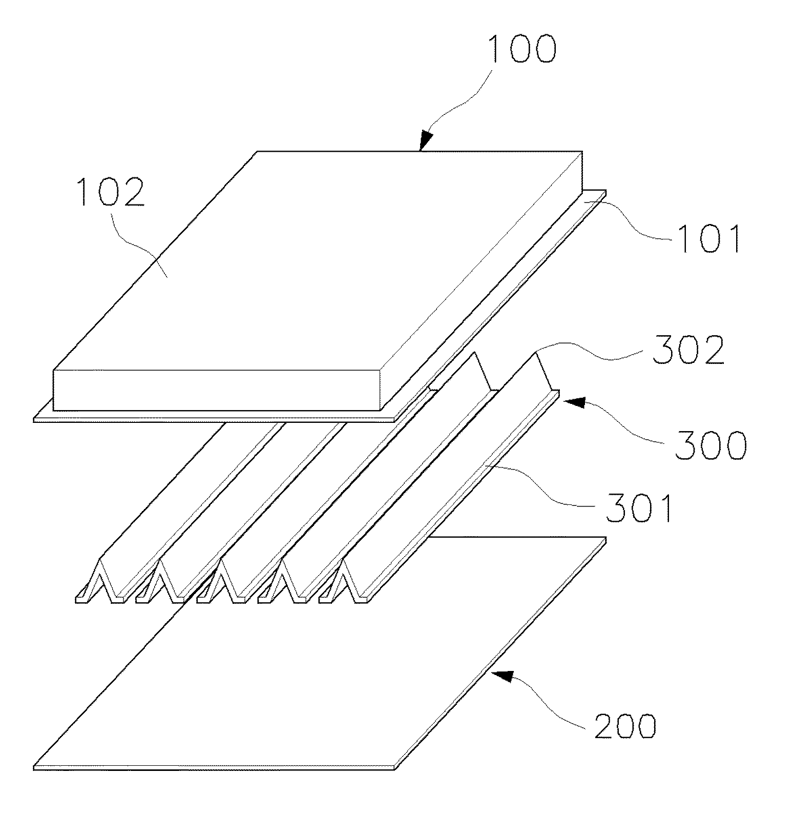
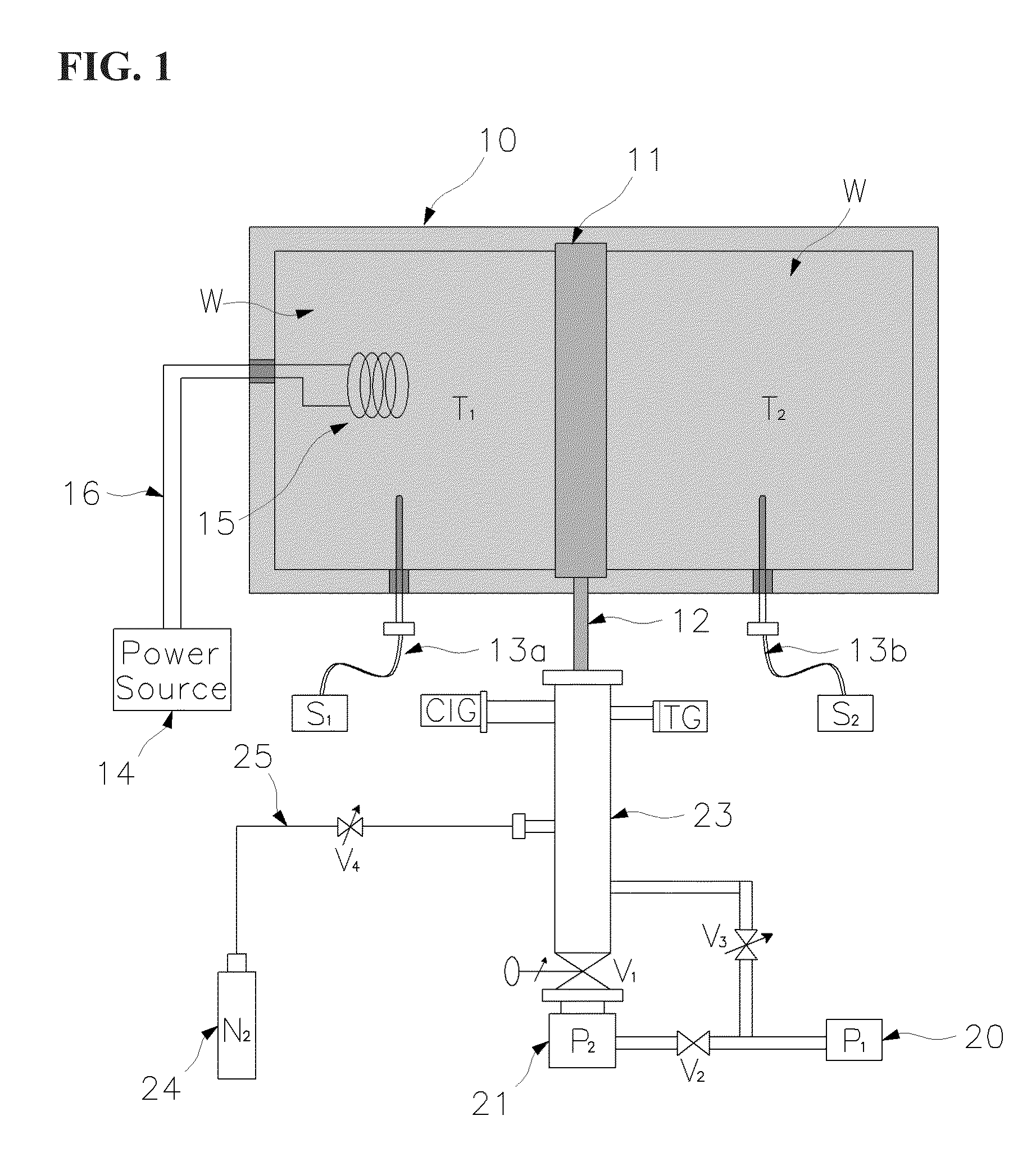
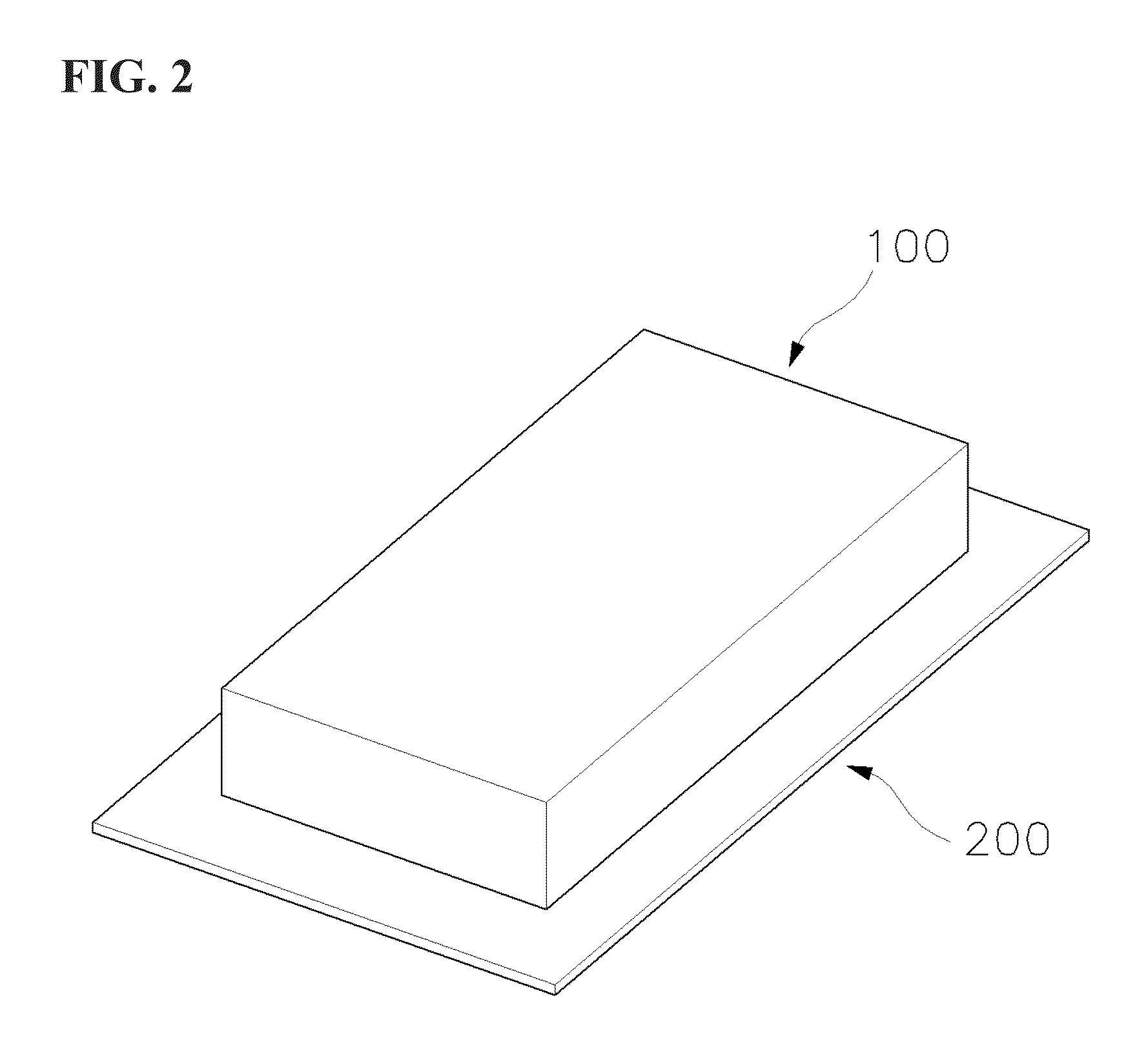
[0076]To assess the insulation characteristics of the vacuum insulation panels according to the present invention, thermal conductivity with respect to the degree of vacuum was measured using the device shown in FIG. 1. A vacuum insulation panel according to the present invention was prepared. For comparison, an insulation panel filled with glass wools and an insulation panel having a thick stainless steel plates between which no filler is filled were prepared.

[0077]1. Comparison of Thermal Conductivity

[0078]1) Device (FIG. 1)

[0079]A insulation box (10) includes a high temperature section (H) and a low temperature section (C). The temperature of the high temperature section (H) can be changed by using a heater and maintained at a certain temperature. The temperature (T1) of the high temperature section (H) and the temperature (T2) of the low temperature section (C) are measured by a temperat...


PUM


Abstract

The present invention relates to a vacuum insulation panel to be used as an insulation material, which panel has an improved structure to improve insulation properties over conventional vacuum insulation panels filed with fillers within outer plates. The present panel includes a spacer within vacuumed space, thereby supporting the structure of outer plate against atmospheric pressure and minimizing conductive thermal transfer.

Description

CROSS-REFERENCE TO RELATED APPLICATIONS[0001]This application claims under 35 U.S.C. §119(a) the benefit of Korean Application No. 10-2010-0073704 filed Jul. 29, 2010, the entire contents of which are incorporated herein by reference.TECHNICAL FIELD[0002]The present invention relates to a vacuum insulation panel to be used as an insulation material. More particularly, it relates to a vacuum insulation panel having an improved structure to improve insulation properties over conventional vacuum insulation panels filed with fillers within outer plates. The present panels include a spacer within a vacuumed space, thereby supporting the structure of the outer plates of the panels against atmospheric pressure and minimizing conductive thermal transfer. The present panels are provided with diffusion or non-diffusion getters disposed on the inner surface of the panel, thereby maintaining the gas pressure inside the panel to be 10−3 torr or lower.BACKGROUND ART[0003]Recognizing that minimizi...

Claims


Application Information

Patent Timeline
IPC IPC(8): E04B1/80B32B1/06B32B3/12
CPCE04B1/803F16L59/075Y02B80/12Y10T428/231Y02B80/10Y02A30/242
Inventor PARK, RAE JUN
Owner XL CO LTD
Why Eureka
Try Eureka