
Systems, Methods, and Apparatuses for Negative-Charge-Pump-Based Antenna Switch Controllers Utilizing Battery Supplies

a negative-charge pump and antenna switch technology, applied in the direction of transmission, electrical equipment, etc., can solve the problems of high cost of conventional antenna switch technology such as gaas phemt and silicon-on-sapphire (sos), and significant integration disadvantages

Inactive Publication Date: 2013-01-31
SAMSUNG ELECTRO MECHANICS CO LTD
View PDF10 Cites 33 Cited by
  • Summary
  • Abstract
  • Description
  • Claims
  • Application Information

AI Technical Summary

Benefits of technology

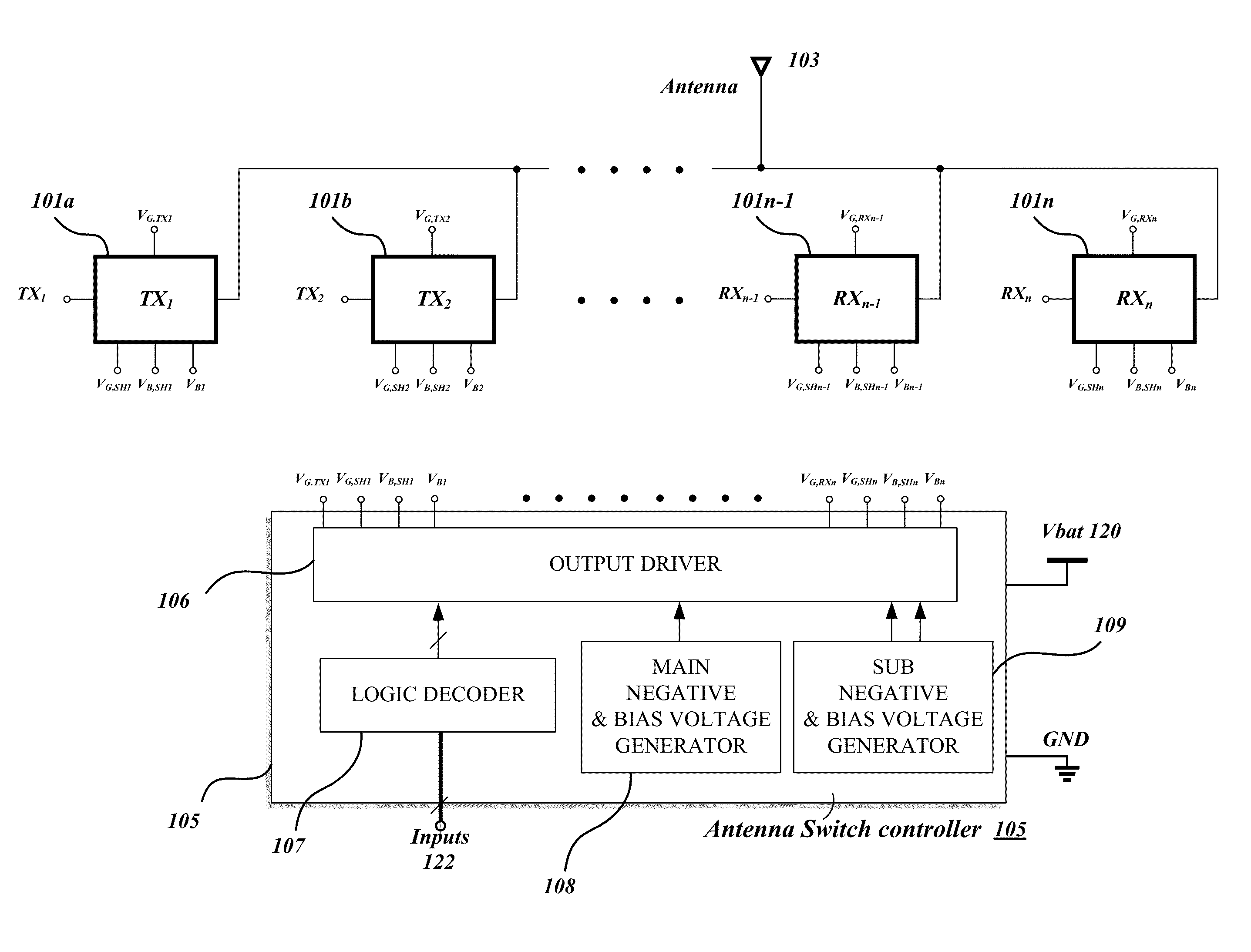
The patent is about a device that controls the switching of antennas. It includes multiple antenna switches, each containing many transistors. One of these switches is activated when transmitting or receiving RF signals. The device also has a voltage generator that generates a constant internal supply voltage, regardless of changes in external voltage. A clock buffer generates clock signals from this constant internal voltage. A charge pump then uses these clock signals to create a stable negative voltage, which is used to bias one or more of the disabled antenna switches. This allows for efficient and reliable control of the antennas, even in situations where the external supply voltage is not stable.

Problems solved by technology

As the market drives integration of multiple standards and multiple bands into a single device, the complexity of the control scheme increases as does requirements for antenna switch performance.
However, conventional technologies used for antenna switches such as GaAs pHEMT and silicon-on-sapphire (SOS) are expensive and have significant disadvantages in integration.

Method used


Image

  • Systems, Methods, and Apparatuses for Negative-Charge-Pump-Based Antenna Switch Controllers Utilizing Battery Supplies
  • Systems, Methods, and Apparatuses for Negative-Charge-Pump-Based Antenna Switch Controllers Utilizing Battery Supplies
  • Systems, Methods, and Apparatuses for Negative-Charge-Pump-Based Antenna Switch Controllers Utilizing Battery Supplies

Examples


Embodiment Construction

[0014]Embodiments of the invention now will be described more fully hereinafter with reference to the accompanying drawings, in which some, but not all embodiments of the invention are shown. Indeed, these inventions may be embodied in many different forms and should not be construed as limited to the embodiments set forth herein; rather, these embodiments are provided so that this disclosure will satisfy applicable legal requirements. Like numbers refer to like elements throughout.

[0015]Embodiments of the invention may provide systems, methods, and apparatuses for negative-charge-pump-based antenna switch controllers utilizing battery supplies. Example antenna switch controllers may be fabricated using various silicon-based processes, including silicon-on-insulator (SOI) processes utilizing SOI substrates. In addition, example antenna switch controllers may utilize complementary metal-oxide-semiconductor (CMOS) technology. Likewise, example antenna switch controllers can control mu...


PUM


Abstract

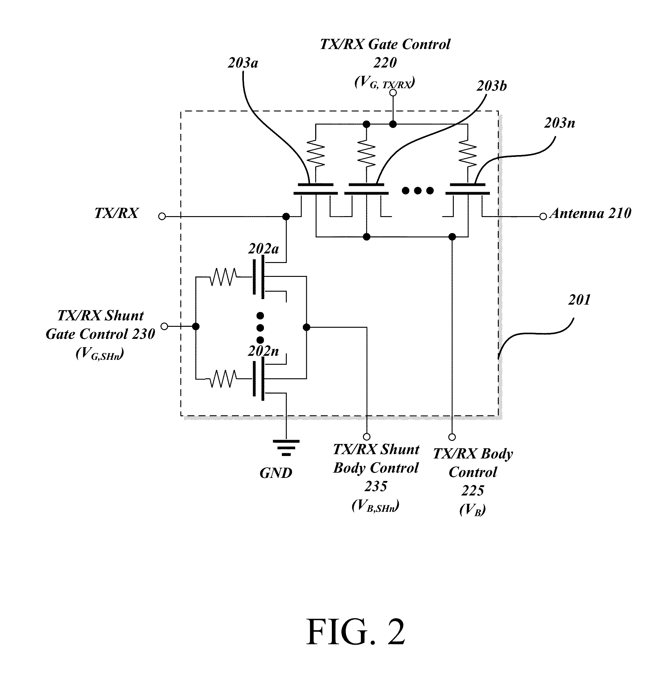
Systems, methods, and apparatuses may provide for antenna switch controllers. An example antenna switch controller may include: a plurality of antenna switches commonly connected to one or more antennas, where each of the plurality of antenna switches includes a plurality of stacked transistors, where one of the plurality of antenna switches is enabled when transmitting or receiving one or more radio frequency (RF) signals via the one or more antennas; a voltage generator that receives an external supply voltage from a battery, where the voltage generator generates an internal supply voltage, where the internal supply voltage remains constant despite fluctuations in the external supply voltage from the battery; a clock buffer that generates clock signals from the constant internal supply voltage; and a charge pump that receives the clock signals and generates a constant negative voltage, where the constant negative voltage is for biasing of one or more of the plurality of antenna switches that are disabled.

Description

FIELD OF THE INVENTION[0001]Embodiments of the invention relate generally to antenna switch controllers, and more particularly, to negative-charge-pump-based antenna switch controllers utilizing battery supplies.BACKGROUND OF THE INVENTION[0002]As wireless communication evolves, there is an increased demand to support multiple standards in a single cellular device. Each standard can require multiple power amplifiers (PAs) and low noise amplifiers (LNAs) in order to cover multiple bands. Because those PAs and LNAs may have to transmit and receive a radio frequency (RF) signal through a shared antenna, an antenna switch is an essential component for selecting a communications block for transmission or reception of an RF signal. Accordingly, a multi-port antenna switch is the one of the key building blocks in the RF front-end circuits for multi-standard cellular devices.[0003]As the market drives integration of multiple standards and multiple bands into a single device, the complexity ...

Claims


Application Information

Patent Timeline
Patent Type & Authority Applications(United States)
IPC IPC(8): H04B1/44
CPCH04B1/48
Inventor CHO, CHANGHYUKCHA, JEONGWONAHN, MINSIKLEE, CHANG-HOWOO, WYANGMYONGCHANG, JAE JOON
Owner SAMSUNG ELECTRO MECHANICS CO LTD
Learn More