Composite Bone Graft Kit

a bone graft and bone graft technology, applied in the field of bone graft delivery kits, can solve the problems of pain and/or nerve damage, degeneration of the spine, destabilization of the spine,

Active Publication Date: 2013-01-31
SPINESMITH PARTNERS
View PDF5 Cites 17 Cited by
  • Summary
  • Abstract
  • Description
  • Claims
  • Application Information

AI Technical Summary

Benefits of technology

[0007]This invention provides a solution to the problems and disadvantages described above by providing a combined synthetic an

Problems solved by technology

Due to trauma, disease, and/or aging, the spine may be subject to degeneration.
This degeneration may destabilize the spine and cause pain and/or nerve damage.
Currently available synthetic bone grafts, however, are typically not optimal and natural autologous bone grafts are in limi

Method used


Image

  • Composite Bone Graft Kit
  • Composite Bone Graft Kit
  • Composite Bone Graft Kit

Examples


Embodiment Construction

[0017]The present invention relates a composite bone graft, composite bone graft delivery kit and method for use.

Composite Bone Graft

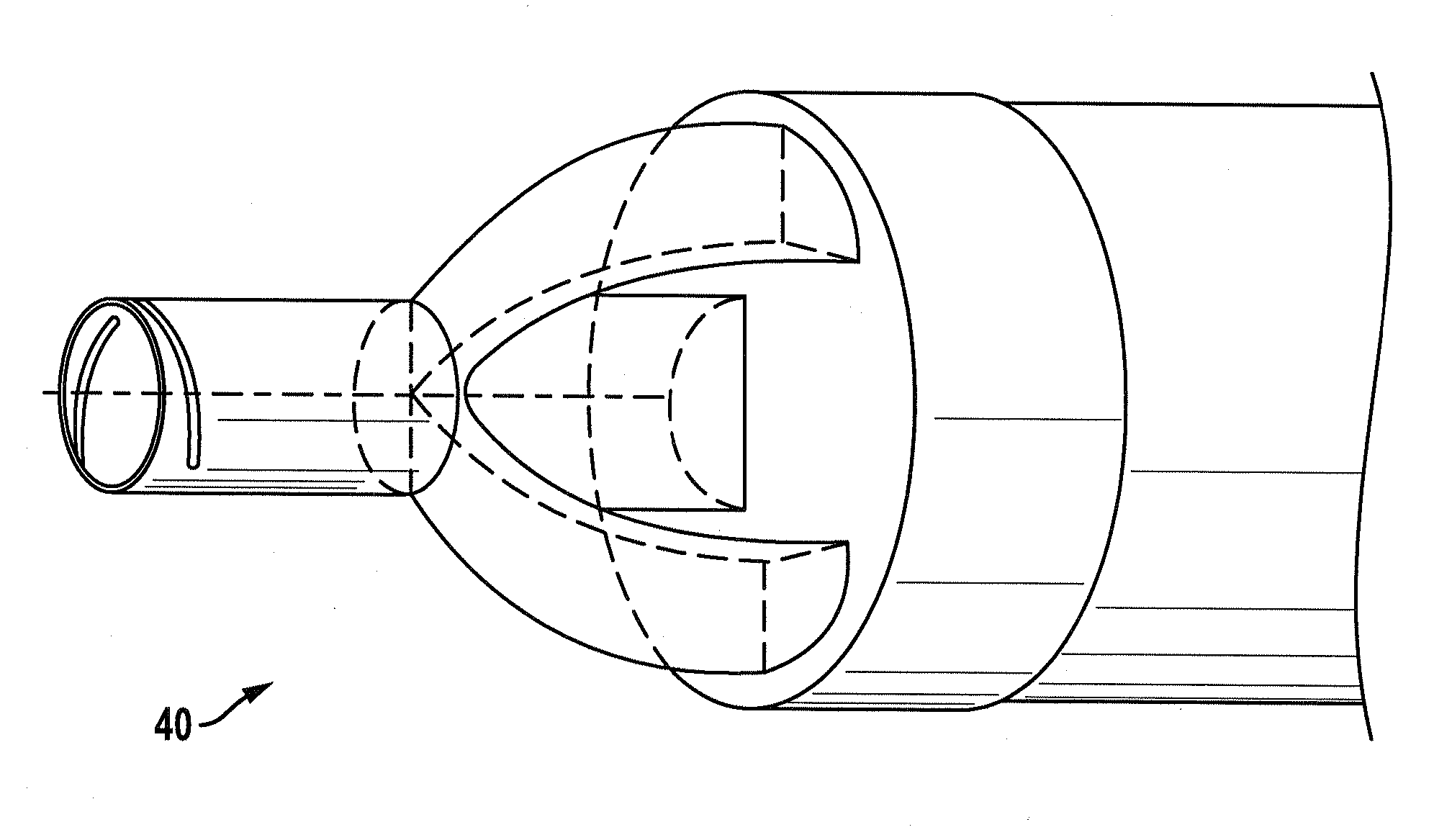
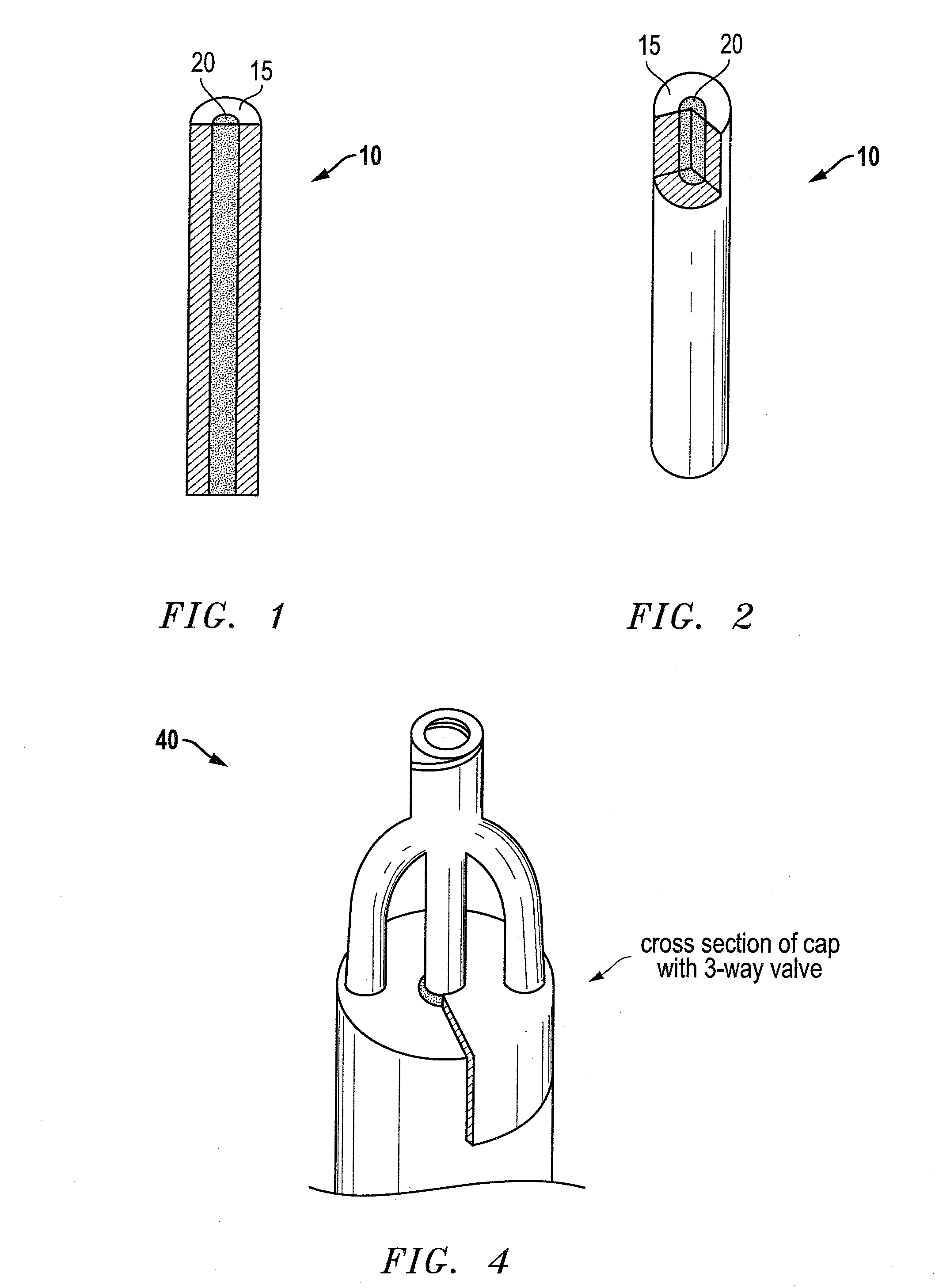
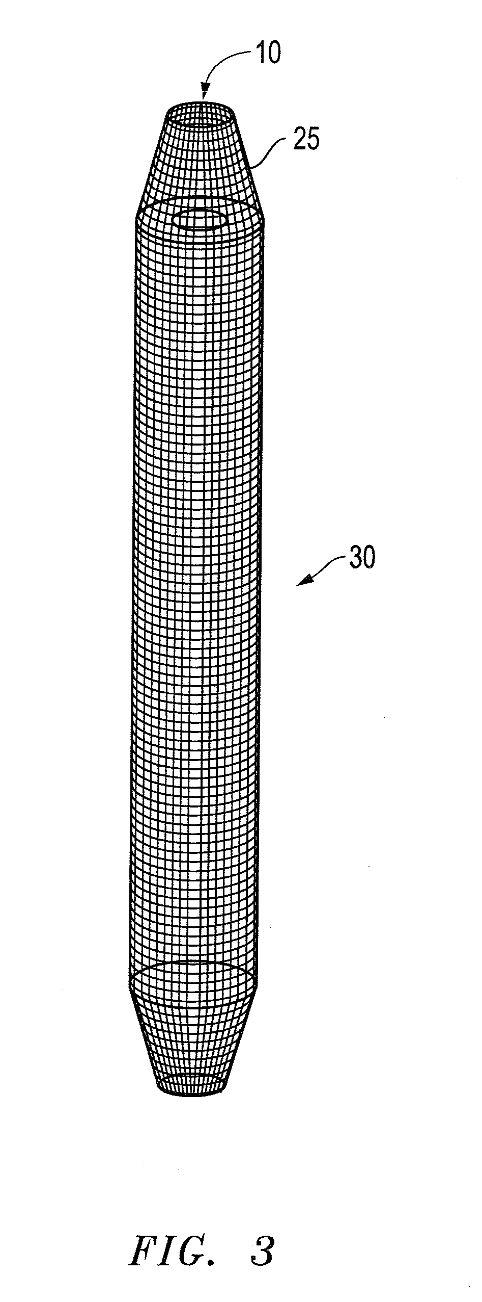
[0018]The composite graft combines allograft or autograft bone and a synthetic bone substitute to form a composite graft that can be used as a topical onlay for fusion grafting in, for example, the posterolateral gutters of the spine, across a fusion segment. The composite graft is formed prior to introduction into or onto the patient.

[0019]In one embodiment, the inner core of the graft may comprise a synthetic bone substitute materials (which are sometimes referred to as bone scaffold materials), such as beta-tricalcium phosphate (BTCP), hydroxyapetite, polyglycolic-polylactid acid (PGLA), poly-lactic acid (PLA), or other synthetics. Allograft or autograft bone may be packed around the synthetic core. The composite is typically formed in concentric cylindrical shells. In one embodiment, the inner cylindrical shell is removed after the core and surroun...


PUM


Abstract

A composite bone graft which comprises an allograft bone component; a synthetic bone substitute, wherein the synthetic bone substitute is in contact with the allograft bone component. The composite is arranged in a core/outer layer structure.

Description

[0001]This applications claims priority to U.S. provisional application Ser. No. 61 / 462,096, filed Jan. 28, 2011, incorporated herein in its entirety by reference.FIELD OF THE INVENTION[0002]The invention herein relates generally to the field of spinal fusion. In particular, this invention is drawn to a bone graft delivery kit and associated methods of use.BACKGROUND OF THE INVENTION[0003]The spine can be considered to be a series of movable segments made up of vertebrae and discs. Due to trauma, disease, and / or aging, the spine may be subject to degeneration. This degeneration may destabilize the spine and cause pain and / or nerve damage. Medical procedures are often required to either ease back pain, repair damage, or to prevent future damage.[0004]One procedure that is often used to treat back pain or spinal damage is spinal fusion. Spinal fusion is a surgical technique used to combine (or fuse) two or more adjacent vertebrae. Supplemental bone tissue is used in conjunction with t...

Claims


Application Information

Patent Timeline
IPC IPC(8): A61F2/28
CPCA61F2310/00293A61F2002/4495A61F2/28A61L2430/02A61F2002/30909A61F2002/2835A61F2310/00359A61F2/44A61L27/365A61F2/4644A61L27/3608
Inventor BURKINSHAW, BRIAN
Owner SPINESMITH PARTNERS
Why Eureka
Try Eureka