Heat exchanger for thermoelectric generators

a heat exchanger and thermoelectric generator technology, applied in the direction of machines/engines, lighting and heating apparatus, laminated elements, etc., can solve the problems of reducing the overall available energy, reducing efficiency, and inefficient work of thermoelectric generators, so as to increase the overall heat flow, reduce the cost of heat exchange, and increase the temperature difference between conductors

Inactive Publication Date: 2013-02-07
ROBERT BOSCH GMBH
View PDF9 Cites 6 Cited by
  • Summary
  • Abstract
  • Description
  • Claims
  • Application Information

AI Technical Summary

Benefits of technology

[0011]The heat exchanger proposed according to the exemplary embodiments and / or exemplary methods of the present invention, having an adapted rib density for thermoelectric generators, makes possible an effective exhaust gas heat recapture, which in turn makes it possible to capture electric current from this otherwise unused energy, which is able to be utilized for different systems of the passenger car, and thus contributes decisively to saving fuel, reduces the CO2 emission and drops pollutant emissions. Thereby thermoelectric generators improve the energy efficiency, environmental compatibility and economy, and at the same time are robust, maintenance-free and adaptable to various fields of application.
[0012]In typical exhaust gas applications, continuous ribbing would lead to a continual reduction in the TEG hot side temperature in the flow direction, since the heat transfer coefficients change only slightly in the flow direction and the TEG hot side temperature continually follows the greatly dropping exhaust gas temperature. The result is that the thermoelectric generators work inefficiently in the last rows of the heat exchanger because of the slight temperature difference, which lowers the efficiency, and because of the low heat flow density. Above all, if the admissible maximum temperature is limited by the TEG material, for example, the wall temperature at the intake of the heat exchanger has to be limited to the admissible maximum temperature, and consequently it lowers the overall available energy. Using the rib density adapted as provided by the exemplary embodiments and / or exemplary methods of the present invention, one is able to achieve a substantially more efficient utilization of the heat flow than when the ribbing is constructed equidistantly.
[0014]One advantageous comparability of the TEG hot side temperature may be achieved by an increase in the heat transfer in the flow direction. This may be achieved by a subdivision of the longitudinal ribs and an increasing rib density in the flow direction. If a maximum admissible TEG temperature is limiting the TEG hot side temperature at the intake, a higher thermal output of the heat exchanger is able to be achieved by an increasing rib density. This method may be used both for the wavy ribs usual in heat exchangers, such as herringbone ribs, and for flat ribs. Moreover, flat and wavy ribs may be combined. For the same heat transfer, wavy ribs have a lower rib density, and thus a reduced weight, but also lower strength. They consequently have advantages in areas of the heat exchanger in which a high heat transfer is required. In areas having a low heat transfer, more densely packed flat ribs may be used under certain circumstances, if an external prestressing force is applied to the system.
[0016]A further advantage is an increased overall heat flow. The greater the temperature differences between the conductors, the more current is able to be produced by the thermoelectric generators. The thermoelectric generators work inefficiently in the last rows of the heat exchanger because of the slight temperature difference, and because of the low heat flow density. Above all, if the admissible maximum temperature is limited (for instance, by the TEG material), the wall temperature at the intake of the heat exchanger has to be limited to the admissible maximum temperature, and consequently it lowers the overall available energy. Because of the adapted rib density, a comparability of the temperature difference and the heat flow density is achieved, which contributes to a more efficient utilization of the thermoelectric generators.
[0017]An adaptation of the rib density to the heat flow is especially meaningful for the application in thermoelectric generators, since thereby the thermoelectric modules in the longitudinal direction of the exhaust gas perceive similar exhaust gas output, in spite of a reduction in the exhaust-gas temperature. Because of this, active electrical output is generated in the different thermoelectric module rows, which reduces demand on the DC motor controller.

Problems solved by technology

The result is that the thermoelectric generators work inefficiently in the last rows of the heat exchanger because of the slight temperature difference, which lowers the efficiency, and because of the low heat flow density.
Above all, if the admissible maximum temperature is limited by the TEG material, for example, the wall temperature at the intake of the heat exchanger has to be limited to the admissible maximum temperature, and consequently it lowers the overall available energy.

Method used


Image

  • Heat exchanger for thermoelectric generators
  • Heat exchanger for thermoelectric generators
  • Heat exchanger for thermoelectric generators

Examples


Embodiment Construction

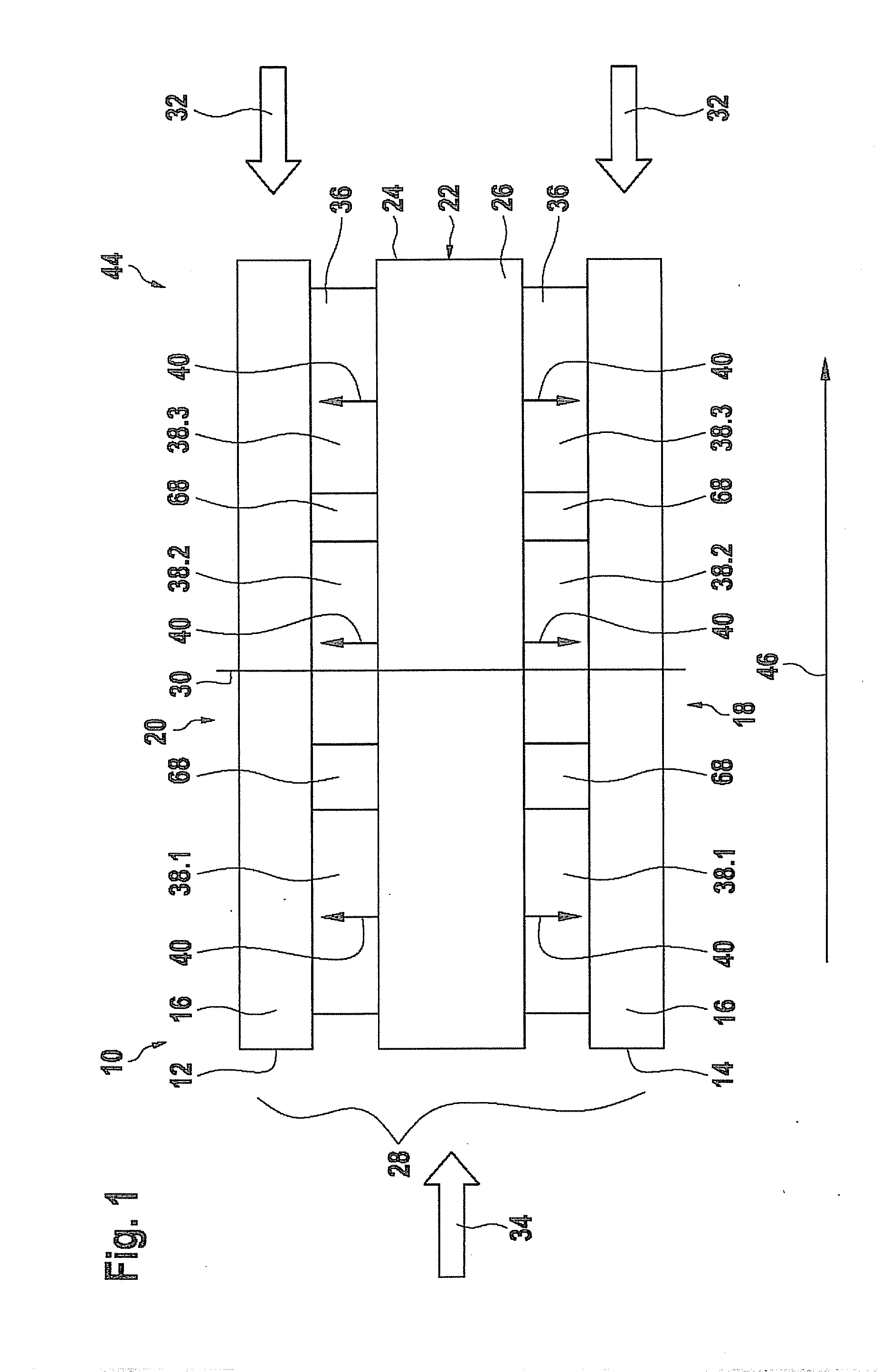
[0024]FIG. 1 represents a possible layout of a heat exchanger having ribbed heating channels and three rows of thermoelectric generators (TEG) in the flow direction.

[0025]In one possible type of embodiment, a heat exchanger 10 may have two channels 12, 14 for a cooling medium 16 as a heat sink. The one channel 12 for cooling medium 16 runs on a lower side 18 of heat exchanger 10, in this context, and second channel 14 for cooling medium 16 runs on upper side 20 of heat exchanger 10.

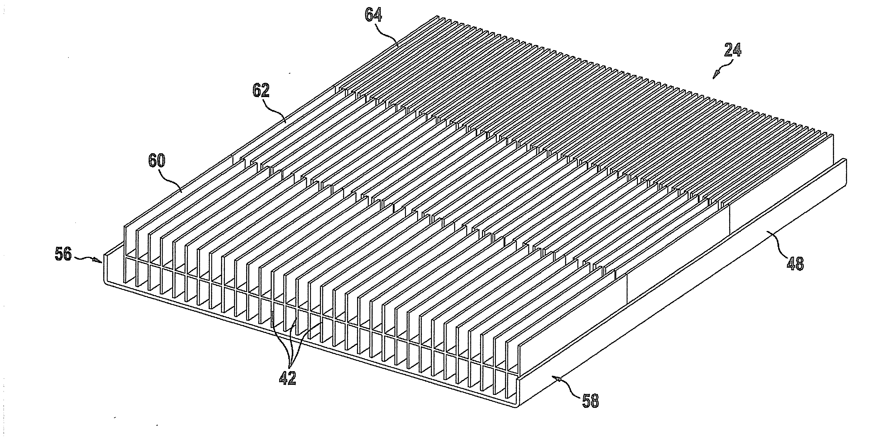
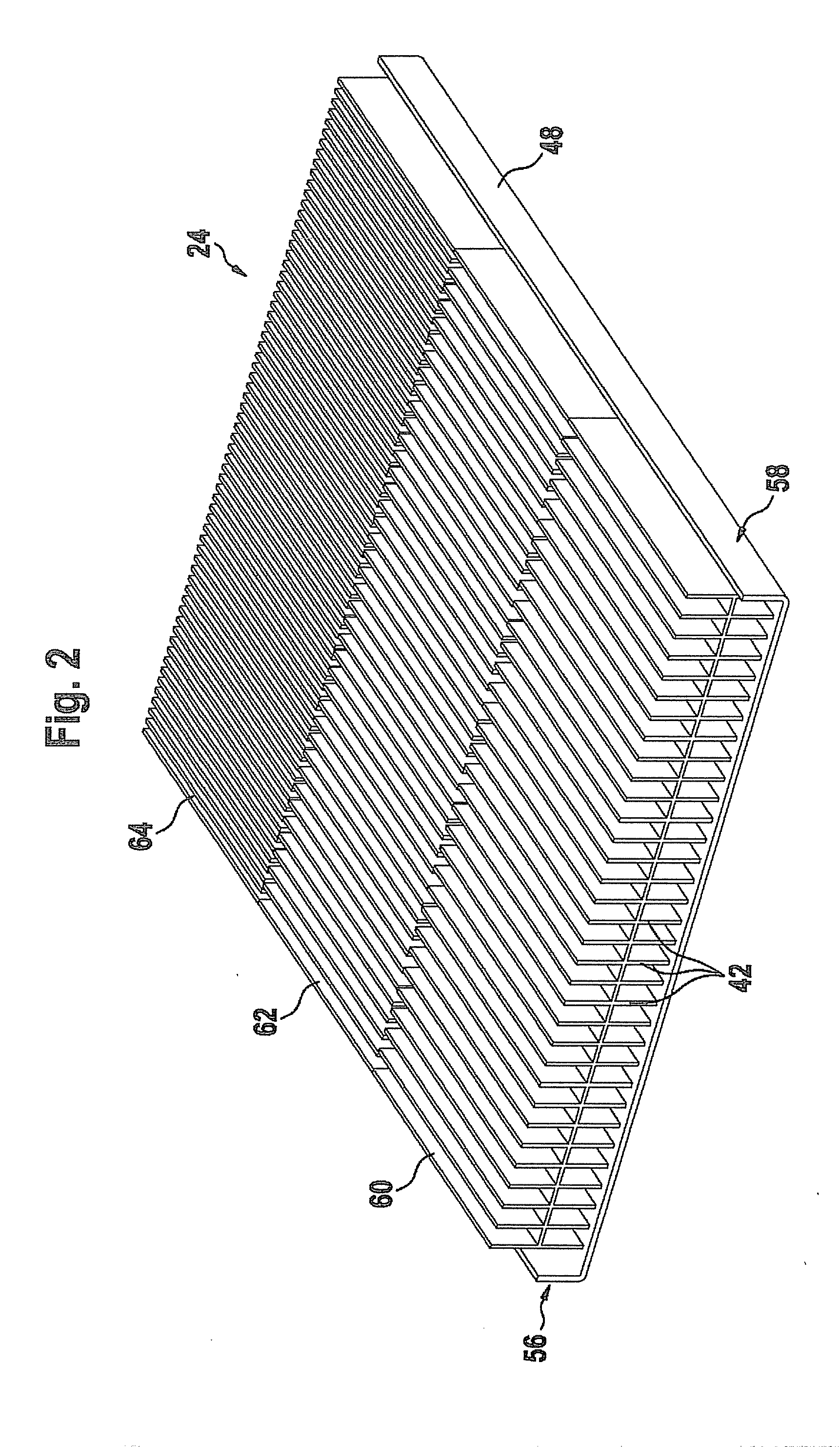
[0026]In the middle 22 of heat exchanger 10 there is located an additional channel 24 for a heating medium 26, which functions as a heat source.

[0027]Channels 12, 14 for cooling medium 16 and channel 24 for a heating medium 26 extend in planes that are parallel to one another and, in the process form a stack 28 having a stack axis 30. As seen along stack axis 30, channels 12, 14 for cooling medium 16 and channel 24 for heating medium 26 are situated alternatingly.

[0028]Other combinations of alternating ch...


PUM


Abstract

A heat exchanger for thermoelectric generators having at least two channels for a cooling medium and at least one channel for a heating medium, the at least one channel for the heating medium being equipped with ribs in the inner region. These ribs are mounted at a number of ribs that increases in the heating flow direction which, among other things, contributes to a more efficient utilization and a comparability of the heat flow.

Description

FIELD OF THE INVENTION[0001]The present invention relates to a heat exchanger for thermoelectric generators.BACKGROUND INFORMATION[0002]The exhaust gas heat produced by motor vehicles which, depending on the model, may amount to up to 35%, is frequently given off to the environment unused. An effective utilization of this heat energy would, however, bring along with it a reduction in fuel consumption.[0003]One possibility of utilizing this exhaust gas heat is thermoelectric generators (TEG). In the free ends of two conductors connected to each other, in response to a temperature difference along the conductors, an electric voltage is produced. Devices for producing energy from the exhaust gas heat are believed to be understood and discussed in German document DE 10 2008 005 334 A1, for example.[0004]For better utilization of the exhaust-gas energy, flow channels, through which the heat-dissipating fluid flows, partially have stiffening devices in the form of ribs, which are normally...

Claims


Application Information

Patent Timeline
Patent Type & Authority Applications(United States)
IPC IPC(8): H01L35/30H01L35/02F01N5/02F28D15/00
CPCF28F3/02F28F2215/04H01L35/30F28F3/025H10N10/13
Inventor GLASER, PATRICK
Owner ROBERT BOSCH GMBH
Why Eureka
Try Eureka